
TM 5-2410-240-23-3
0247
REMOVAL CONTINUED
000247
WARN I N G
Engine coolant is very slippery. Immediately wipe up any spills. Failure to follow this
warning may result in injury to personnel.
N OT E
Tag and mark hoses to aid installation.
Note orientation of connector hose to aid installation.
Plug or cap all hoses and open ports.
Note location of tiedown sraps to aid installation.
t
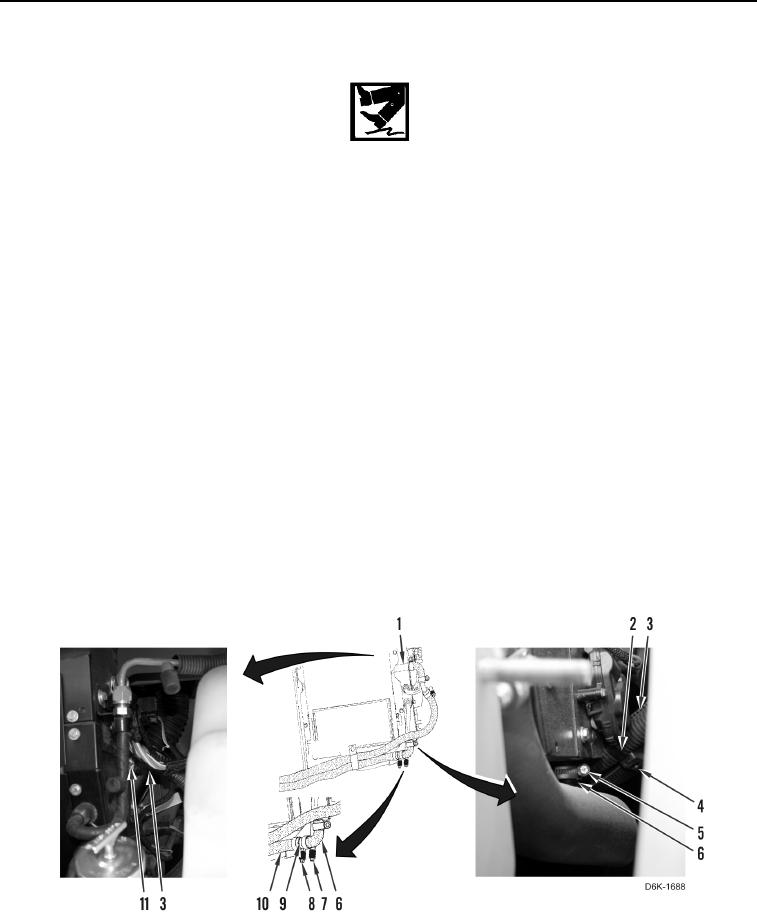
23. Loosen clamp (Figure 12, Item 11) and disconnect upper heater hose (Figure 12, Item 3) from heater core
(Figure 12, Item 1).
24. Remove clamp (Figure 12, Item 11) from upper heater hose (Figure 12, Item 3).
25. Loosen clamp (Figure 12, Item 5) and disconnect connector hose (Figure 12, Item 6) from heater core
(Figure 12, Item 1).
26. Remove clamp (Figure 12, Item 5) from connector hose (Figure 12, Item 6).
27. Remove tiedown strap (Figure 12, Item 2) from upper heater hose (Figure 12, Item 3) and A/C hose (Figure 12,
Item 4). Discard tiedown strap.
28. Remove clamp (Figure 12, Item 7) from connector hose (Figure 12, Item 6).
29. Remove connector hose (Figure 12, Item 6) from connector (Figure 12, Item 9).
30. Remove clamp (Figure 12, Item 8) and connector (Figure 12, Item 9) from lower heater hose (Figure 12,
Item 10).
Figure 12. Heater Hoses and Clamps in Left Rear Access.
0247