
TM 5-2410-240-23-3
0247
INSTALLATION CONTINUED
000247
N OT E
Remove plugs or caps from hoses and open ports.
Install hoses and tiedown straps as noted during removal.
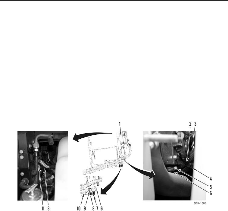
12. Install connector (Figure 19, Item 9) and clamp (Figure 19, Item 8) on lower heater hose (Figure 19, Item 10).
13. Install connector hose (Figure 19, Item 6) and clamp (Figure 19, Item 7) on connector (Figure 19, Item 9).
14. Tighten two clamps (Figure 19, Items 7 and 8).
15. Loosely install clamp (Figure 19, Item 5) on connector hose (Figure 19, Item 6).
16. Connect connector hose (Figure 19, Item 6) on heater core (Figure 19, Item 1) and tighten clamp (Figure 19,
Item 5).
17. Loosely install clamp (Figure 19, Item 11) on upper heater hose (Figure 19, Item 3).
18. Connect upper heater hose (Figure 19, Item 3) on heater core (Figure 19, Item 1) and tighten clamp
(Figure 19, Item 11).
19. Install new tiedown strap (Figure 19, Item 2) on upper heater hose (Figure 19, Item 3) and A/C hose
(Figure 19, Item 4).
Figure 19. Heater Hoses and Clamps in Left Rear Access.
0247