
TM 5-2410-240-23-3
0249
INSTALLATION CONTINUED
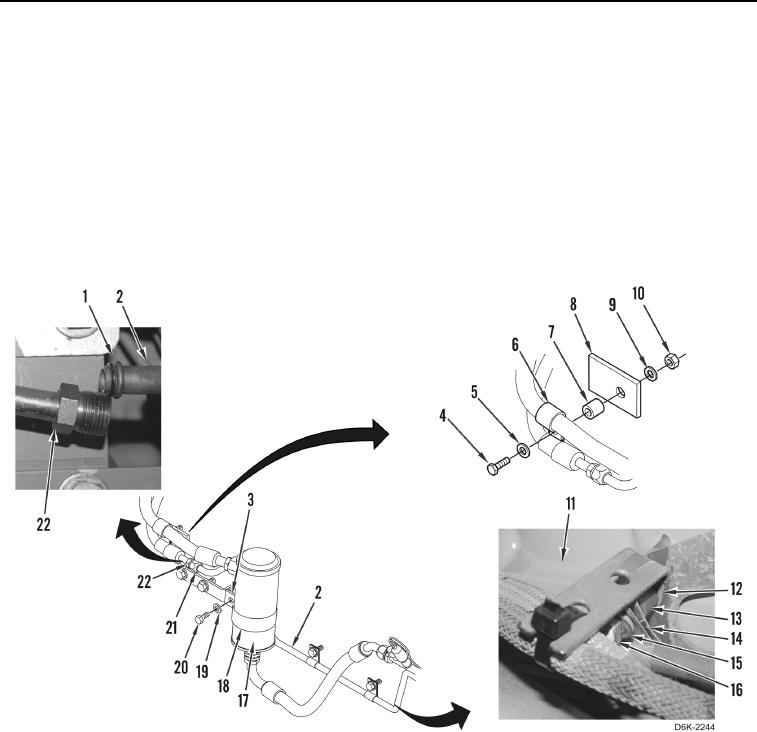
10. Position accumulator (Figure 4, Item 17) on machine, install two half clamps (Figure 4, Item 18), spacer
(Figure 4, Item 3), washer (Figure 4, Item 19), and bolt (Figure 4, Item 20) on accumulator.
11. Install two clamps (Figure 4, Item 14) on A/C line (Figure 4, Item 2).
12. Position two brackets (Figure 4, Item 12) on engine (Figure 4, Item 11).
13. Install two clamps (Figure 4, Item 14), one spacer (Figure 4, Item 13), washers (Figure 4, Item 15), and bolts
(Figure 4, Item 16) on engine (Figure 4, Item 11).
14. Install new O-ring (Figure 4, Item 1) on A/C line (Figure 4, Item 2), and connect A/C hose (Figure 4, Item 22) on
A/C line (Figure 4, Item 2).
15. Install spacer (Figure 4, Item 7), two clamps (Figure 4, Item 6), bolt (Figure 4, Item 4), and washer (Figure 4,
Item 5), washer (Figure 4, Item 9), and nut (Figure 4, Item 10) on bracket (Figure 4, Item 8)
Figure 4. A/C Line, O-ring, and Retaining Hardware.
0249
END OF TASK