
TM 5-2410-240-23-3
0249
REMOVAL
000249
C AU T I O N
Cap or plug A/C line and A/C hose during removal to protect against contamination.
Failure to follow this caution may result in equipment damage.
N OT E
Tag and mark A/C line and A/C hose to aid installation.
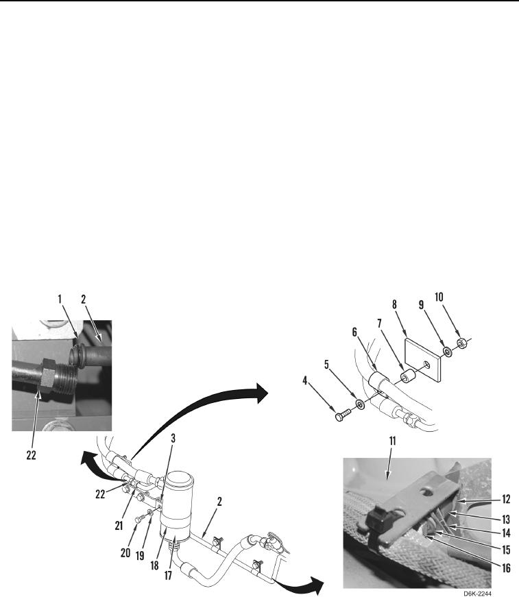
1. Remove bolt (Figure 1, Item 4), washer (Figure 1, Item 5), two clamps (Figure 1, Item 6), spacer (Figure 1,
Item 7), washer (Figure 1, Item 9), and nut (Figure 1, Item 10) from bracket (Figure 1, Item 8).
2. Loosen fitting (Figure 1, Item 21) and disconnect A/C hose (Figure 1, Item 22) from A/C line (Figure 1, Item 2).
3. Remove O-ring (Figure 1, Item 1) from A/C line (Figure 1, Item 2). Discard O-ring.
4. Remove two bolts (Figure 1, Item 16), washers (Figure 1, Item 15), clamps (Figure 1, Item 14), one spacer
(Figure 1, Item 13), and bracket (Figure 1, Item 12) from engine (Figure 1, Item 11). Position brackets aside.
5. Remove two clamps (Figure 1, Item 14) from A/C line (Figure 1, Item 2).
6. Remove bolt (Figure 1, Item 20), washer (Figure 1, Item 19), spacer (Figure 1, Item 3), and two half clamps
(Figure 1, Item 18) from accumulator (Figure 1, Item 17), and position accumulator aside.
Figure 1. A/C Line, O-ring and Retaining Hardware.
0249
C AU T I O N
Cap or plug A/C hose and all A/C lines and fittings during removal to protect against
contamination. Failure to follow this caution may result in equipment damage.