
TM 5-2410-240-23-3
0249
REMOVAL CONTINUED
N OT E
Tag and mark A/C hose and A/C lines to aid installation.
Note routing and orientation of A/C lines to aid installation.
Note location of tiedown strap to aid installation.
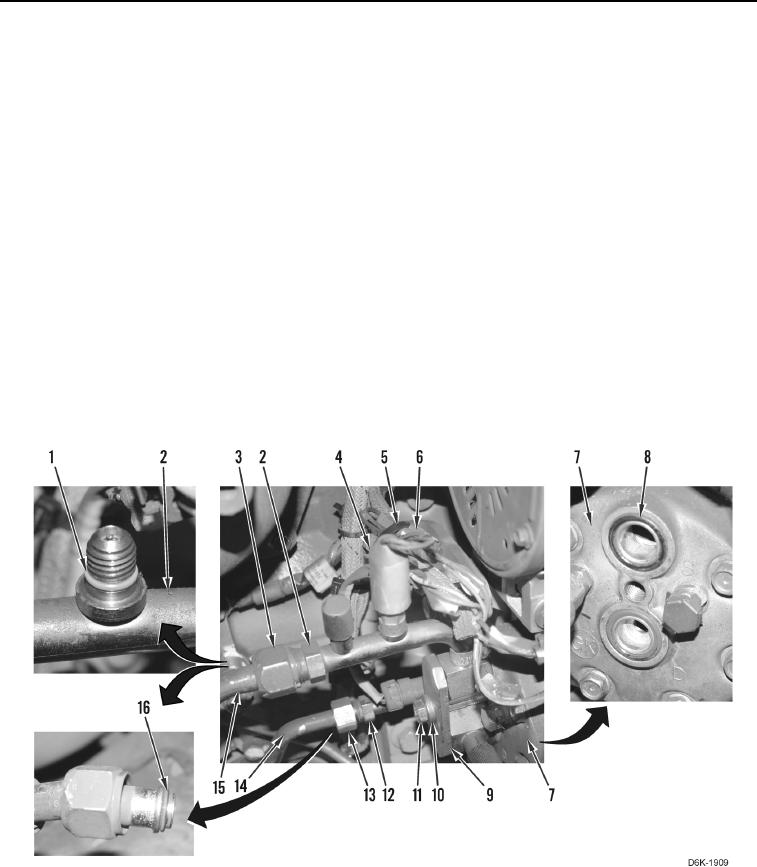
7. Remove tiedown strap (Figure 2, Item 5) from harness connectors (Figure 2, Item 6). Discard tiedown strap.
8. Disconnect low pressure switch (Figure 2, Item 4) from harness connector (Figure 2, Item 6).
9. Remove bolt (Figure 2, Item 11), washer (Figure 2, Item 10), plate (Figure 2, Item 9), and A/C lines (Figure 2,
Items 2 and 12) from A/C compressor (Figure 2, Item 7).
10. Remove two O-rings (Figure 2, Item 8) from A/C compressor (Figure 2, Item 7). Discard O-rings.
11. Loosen fitting (Figure 2, Item 3) and disconnect A/C line (Figure 2, Item 2) from A/C hose (Figure 2, Item 15).
12. Loosen fitting (Figure 2, Item 13) and disconnect A/C line (Figure 2, Item 12) from A/C line (Figure 2, Item 14).
13. Remove A/C line (Figure 2, Item 14) from machine.
14. Remove O-rings (Figure 2, Item 16) from A/C hose (Figure 2, Item 15) and from A/C line (Figure 2, Item 14).
Discard O-rings.
15. Remove low pressure switch (Figure 2, Item 4) and O-ring (Figure 2, Item 1) from A/C line (Figure 2, Item 2).
Discard O-ring.
Figure 2. Low Pressure Switch, O-rings, A/C Lines, and Retaining Hardware.
0249
END OF TASK