
TM 5-2410-240-23-3
0265
INSTALLATION
000265
N OT E
Remove caps or plugs from all hydraulic hoses and fittings before installation.
Install all hoses and electrical connectors as noted during removal.
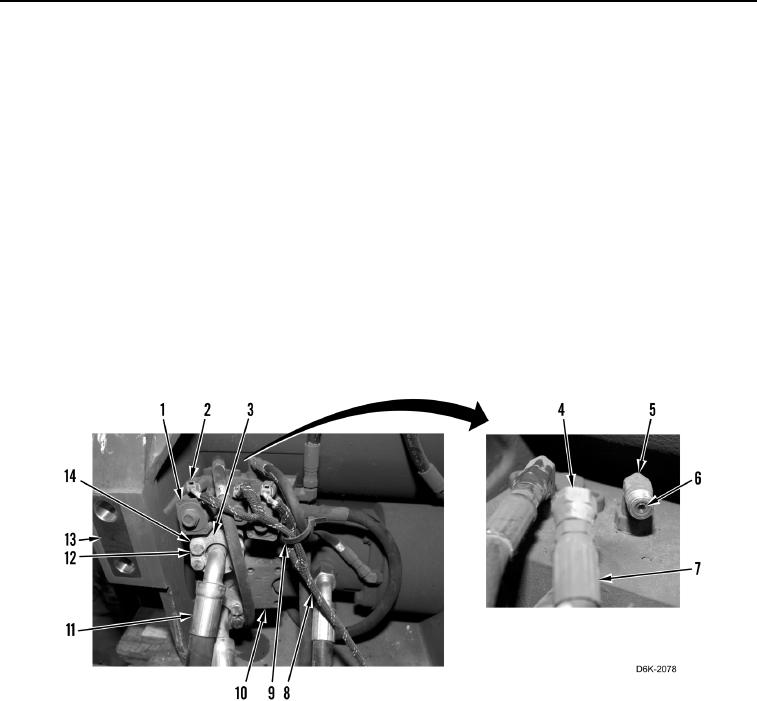
1. Apply lubricating oil on 12 new O-rings (Figure 15, Item 6).
2. Install 12 new O-rings (Figure 15, Item 6) on 10 fittings (Figure 15, Item 5) and two winch hoses (Figure 15,
Item 11).
3. Connect six winch hoses (Figure 15, Item 7) on 10 fittings (Figure 15, Item 5) and tighten fasteners (Figure 15,
Item 4).
4. Install two winch hoses (Figure 15, Item 11), four clamps (Figure 15, Item 3), eight washers (Figure 15,
Item 14), and bolts (Figure 15, Item 12) on motor assembly (Figure 15, Item 10).
5. Install winch harness (Figure 15, Item 8) on winch (Figure 15, Item 13).
6. Connect three electrical connectors (Figure 15, Item 2) on solenoids (Figure 15, Item 1).
7. Install new tiedown strap (Figure 15, Item 9) on winch harness (Figure 15, Item 8) and winch hose (Figure 15,
Item 7).
Figure 15. Winch, Motor Assembly, Hoses, and O-rings.
0265