
TM 5-2410-240-23-3
0270
REMOVAL
000270
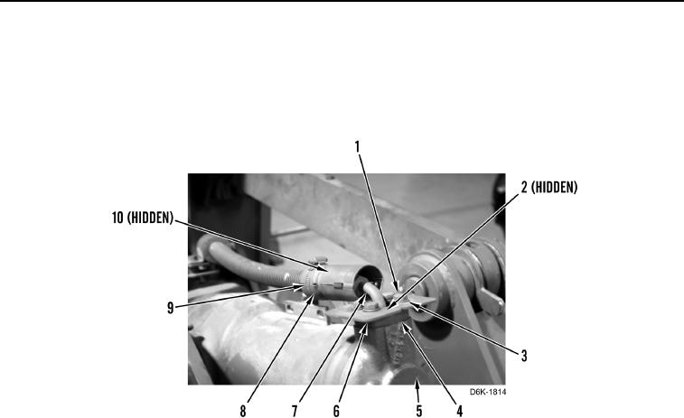
1. Remove clamp (Figure 1, Item 9), shield (Figure 1, Item 8), rubber bushing (Figure 1, Item 10), four bolts
(Figure 1, Item 1), washers (Figure 1, Item 3), two shields (Figure 1, Item 6), flanges (Figure 1, Item 4), and
hose (Figure 1, Item 7) from cylinder (Figure 1, Item 5).
2. Remove O-ring (Figure 1, Item 2) from hose (Figure 1, Item 7). Discard O-ring.
Figure 1. Ripper Lift Cylinder Hydraulic Line - Rear.
0270