
TM 5-2410-240-23-3
0270
REMOVAL CONTINUED
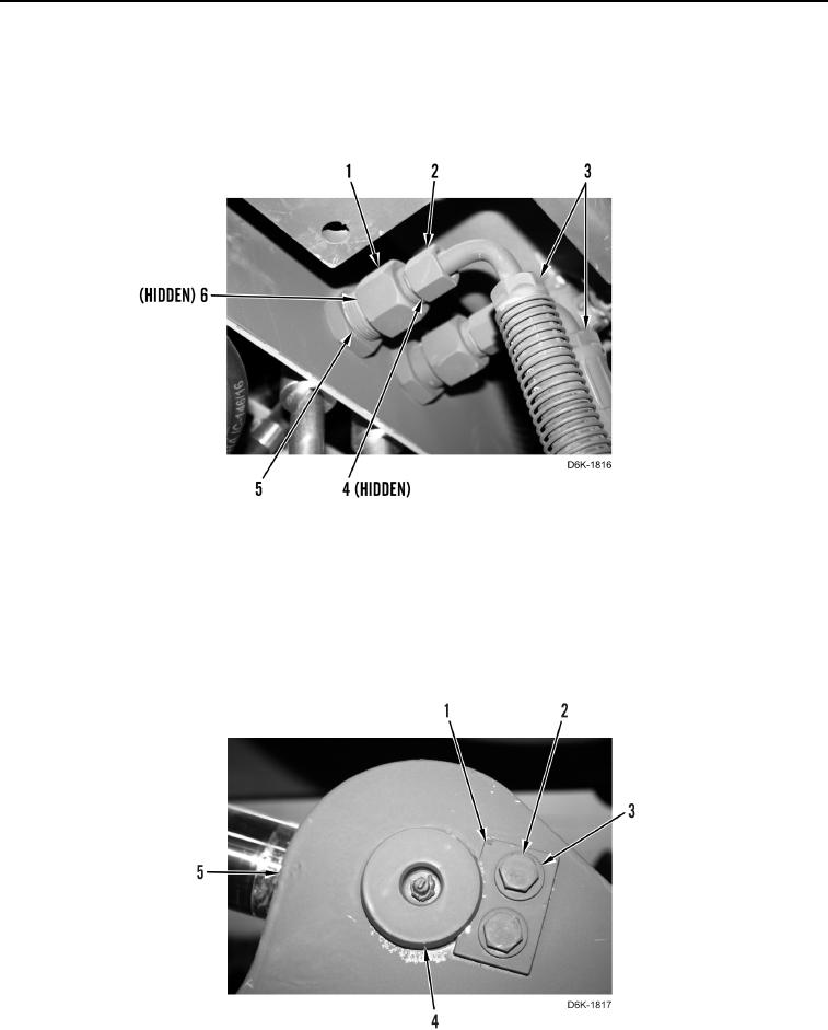
6. Remove two nuts (Figure 3, Item 2) and hoses (Figure 3, Item 3) from reducers (Figure 3, Item 1).
7. Remove two reducers (Figure 3, Item 1) from line fittings (Figure 3, Item 5).
8. Remove four O-rings (Figure 3, Items 4 and 6) from two reducers (Figure 3, Item 1). Discard O-rings.
Figure 3. Ripper Hydraulic Hose Fittings.
0270
N OT E
Note position of pin to aid installation.
9. Remove two bolts (Figure 4, Item 2), washers (Figure 4, Item 3), bar (Figure 4, Item 1), and pin (Figure 4,
Item 4) from ripper (Figure 4, Item 5).
Figure 4. Ripper Lift Cylinder Attachment - Front.
0270