
TM 5-2410-240-23-3
0270
DISASSEMBLY CONTINUED
N OT E
Note position of piston to aid installation.
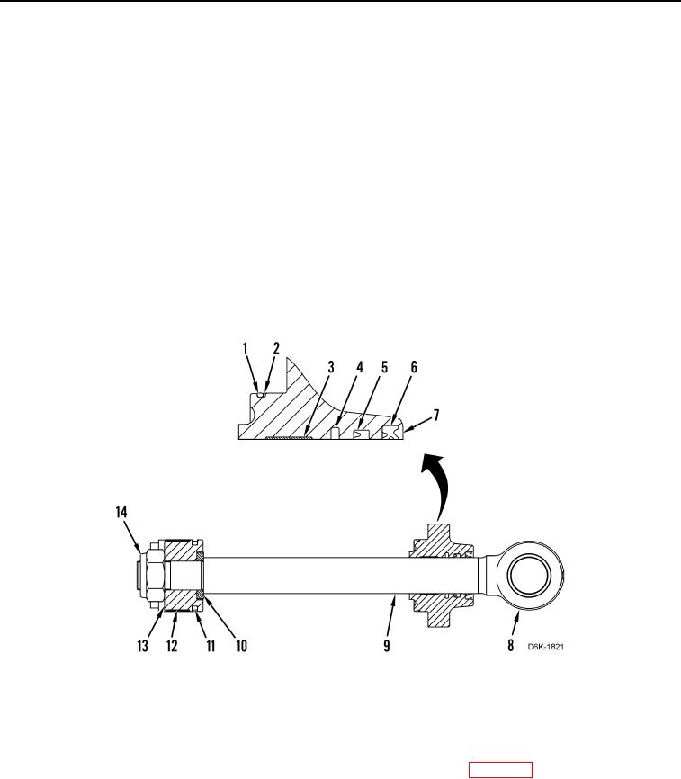
2. Remove locknut (Figure 9, Item 14), piston (Figure 9, Item 13), and cylinder head (Figure 9, Item 7) from rod
(Figure 9, Item 9). Discard locknut.
N OT E
Note position and location of seals to aid installation.
3. Remove three seals (Figure 9, Items 4, 5, and 6), O-ring (Figure 9, Item 1), backup ring (Figure 9, Item 2), and
wear ring (Figure 9, Item 3) from cylinder head (Figure 9, Item 7). Discard seals, O-ring, and wear ring.
4. Remove washer (Figure 9, Item 10), seal (Figure 9, Item 11), and wear ring (Figure 9, Item 12) from piston
(Figure 9, Item 13). Discard washer, seal, and wear ring.
5. Remove sleeve (Figure 9, Item 8) from rod (Figure 9, Item 9).
Figure 9. Ripper Lift Cylinder Head and Rod Components.
0270
END OF TASK
CLEANING AND INSPECTION
000270
Clean and inspect all parts IAW Mechanical General Maintenance Instructions (WP 0282).
END OF TASK