
TM 5-2410-240-23-3
0270
INSTALLATION CONTINUED
N OT E
Perform the following two steps to install left side trunnion bearing. Use these same steps
to install right side trunnion bearing.
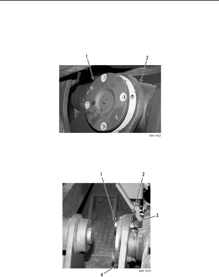
2. Install trunnion bearing (Figure 13, Item 1) on ripper (Figure 13, Item 2).
Figure 13. Ripper Lift Cylinder Trunnion Bearing.
0270
3. Install eight washers (Figure 14, Item 2), four bolts (Figure 14, Item 1), and four nuts (Figure 14, Item 3) on
ripper (Figure 14, Item 4).
Figure 14. Ripper Lift Cylinder Trunnion Bearing Attachment Bolts.
0270