
TM 5-2410-240-23-3
0270
INSTALLATION CONTINUED
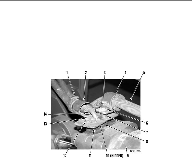
8. Install new O-ring (Figure 17, Item 10) on hose (Figure 17, Item 14).
9. Install hose (Figure 17, Item 14), two flanges (Figure 17, Item 8), shields (Figure 17, Item 11), three washers
(Figure 17, Item 12), and bolts (Figure 17, Item 13) on cylinder (Figure 17, Item 9).
N OT E
Install spacer, clamp, washer, and bolt as noted during removal.
10. Install spacer (Figure 17, Item 7), clamp (Figure 17, Item 4), washer (Figure 17, Item 6), and bolt (Figure 17,
Item 3) on cylinder (Figure 17, Item 9).
11. Install shield (Figure 17, Item 2) and clamp (Figure 17, Item 1) on hose (Figure 17, Item 14).
Figure 17. Ripper Lift Cylinder Hydraulic Line - Front.
0270