• Home
  • Download PDF
  • Order CD-ROM
  • Order in Print
Figure 15. Ripper Lift Cylinder Attachment - Front.
Figure 17. Ripper Lift Cylinder Hydraulic Line - Front.

Field Maintenance Manual 3 D6K Dozer Type I With Winch and Type II With Ripper
Page Navigation
  1031    1032    1033    1034    1035  1036  1037    1038    1039    1040    1041  
img
.
TM 5-2410-240-23-3
0270
INSTALLATION CONTINUED
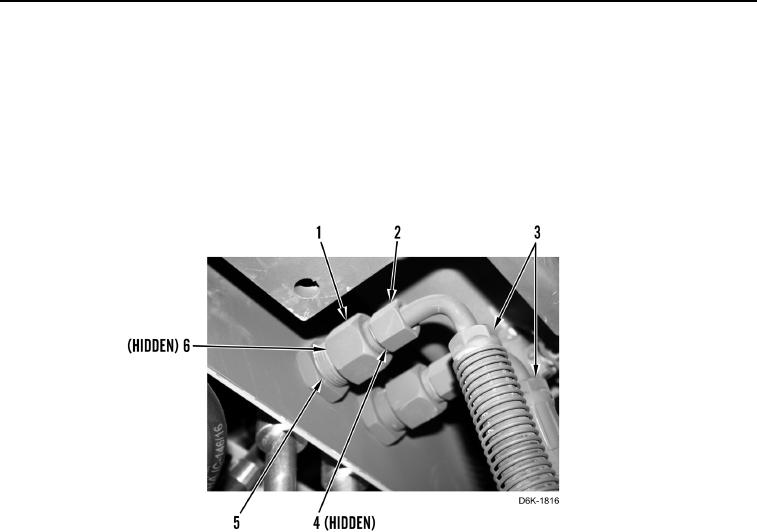
5. Install four new O-rings (Figure 16, Items 4 and 6) on two reducers (Figure 16, Item 1).
6. Install two reducers (Figure 16, Item 1) on line fittings (Figure 16, Item 5).
N OT E
Install hoses as noted during removal.
7. Install two hoses (Figure 16, Item 3) and two nuts (Figure 16, Item 2) on reducers (Figure 16, Item 1).
Figure 16. Ripper Hydraulic Line Fittings.
0270
0270-15


Privacy Statement
Press Release
Contact

© Copyright Integrated Publishing, Inc.. All Rights Reserved.