• Home
  • Download PDF
  • Order CD-ROM
  • Order in Print
Figure 17. Pump and Compensator Operation (Constant Flow).
IMPLEMENT AND STEERING HYDRAULIC SYSTEM CONTINUED

Field Maintenance Manual 1 D7R Dozer Type I With Winch and Type II With Ripper
Page Navigation
  121    122    123    124    125  126  127    128    129    130    131  
img
.
TM 5-2410-241-23-1
0011
IMPLEMENT AND STEERING HYDRAULIC SYSTEM CONTINUED
Piston Motor (Steering)
00011
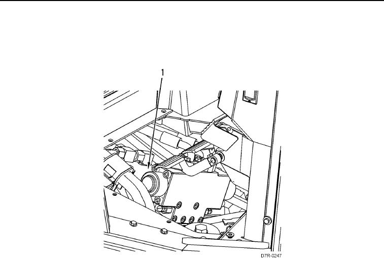
The steering motor (Figure 18, Item 1) is located between the counterbalance valve and an adapter. The adapter is
attached to the frame below the operator's station.
Figure 18. Piston Motor (Steering) Location.
0011
0011-17


Privacy Statement
Press Release
Contact

© Copyright Integrated Publishing, Inc.. All Rights Reserved.