
TM 5-2410-241-23-1
0019
Table 2. Engine Troubleshooting Procedures - Continued.
MALFUNCTION
TEST OR INSPECTION
CORRECTIVE ACTION
91-2 Incorrect Throttle
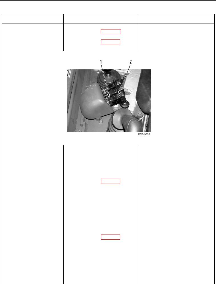
4. Disconnect throttle switch con-
Switch Inputs -
nector RW-C4 (WP 0018,
Continued
Figure 13) (Figure 9, Item 1) from
throttle switch (WP 0018,
Figure 16) (Figure 9, Item 2).
Figure 9. Throttle Switch Connector.
019
5. Hold the throttle switch in the
LOW (tortoise) position
(TM 5-2410-241-10).
6. Using digital multimeter
1. If continuity is found, proceed to
(WP 0296), test for continuity
step 7.
between pin 1 and pin 2 on the
2. If continuity is not found, replace
throttle switch (WP 0018,
throttle switch (WP 0208). Ensure
Figure 16).
all harness connectors are recon-
nected. Verify correct operation of
machine (TM 5-2410-241-10).
7. Hold the throttle switch in the
LOW (tortoise) position
(TM 5-2410-241-10).
8. Using digital multimeter
1. If continuity is found, proceed to
(WP 0296), test for continuity
step 9.
between pin 4 and pin 5 on the
2. If continuity is not found, replace
throttle switch (WP 0018,
throttle switch (WP 0208). Ensure
Figure 16).
all harness connectors are recon-
nected. Verify correct operation of
machine (TM 5-2410-241-10).
0019-32