
TM 5-2410-241-23-1
0020
Table 1. Powertrain Troubleshooting Procedures - Continued.
0020
MALFUNCTION
TEST OR INSPECTION
CORRECTIVE ACTION
1404-5 Transmission Sole-
25. Using a digital multimeter (WP
1. If continuity is found, replace pow-
noid Valve #4 Current
0296), test for continuity between
ertrain ECM (WP 0175). Ensure all
Below Normal - Contin-
pin D on transmission harness
harness connectors are recon-
ued
connector P-C1 (WP 0018,
nected. Verify correct operation of
Figure 56) and pin 1 on transmis-
machine (TM 5-2410-241-10).
sion solenoid valve #4 connector
2. If continuity is NOT found, replace
P-C6 (WP 0018, Figure 74).
transmission sensor harness (WP
0173). Ensure all harness connec-
tors are reconnected. Verify cor-
rect operation of machine (TM 5-
2410-241-10).
1404-6 Transmission Sole-
1. Connect MSD (WP 0016), select
1. If active 1404-6 code is present,
noid Valve #4 Current
Powertrain D7 ECM, and check for
proceed to step 2.
Above Normal
Diagnostic Codes (WP 0013).
2. If no active codes are present, the
problem does NOT exist at this
time. Resume normal operation.
2. Turn ignition switch and battery
disconnect switch to OFF position
(TM 5-2410-241-10).
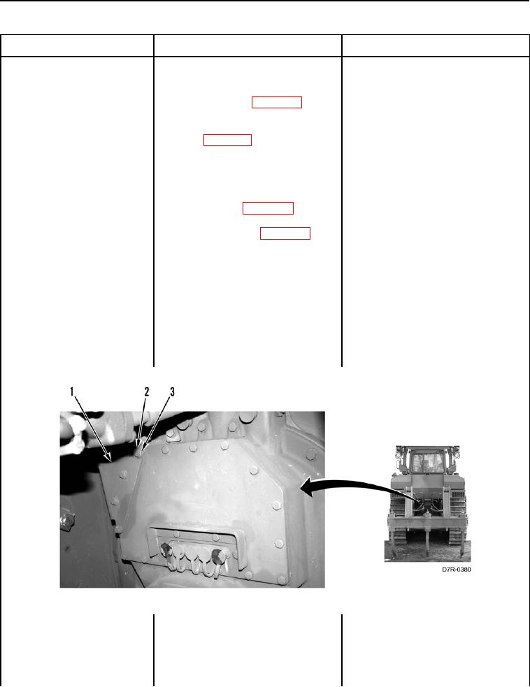
3. Remove four bolts (Figure 68,
Item 2), washers (Figure 68,
Item 3), and guard (Figure 68,
Item 1) from machine.
Figure 68. Guard and Retaining Hardware.
0020