
TM 5-2410-241-23-1
0021
Table 2. Chassis Troubleshooting Procedures - Continued.
0021
MALFUNCTION
TEST OR INSPECTION
CORRECTIVE ACTION
490-3 Hydraulic Lockout
10. Using digital multimeter (WP
1. If continuity is found, replace
Solenoid Voltage Above
0296), test for continuity between
hydraulic lockout switch (WP
Normal - Continued
pin 5 and 6 on hydraulic lockout
0208). Ensure all harness con-
switch (WP 0018, Figure 91).
nectors are reconnected. Verify
correct operation of machine (TM
5-2410-241-10).
2. If continuity is NOT found, pro-
ceed to step 11.
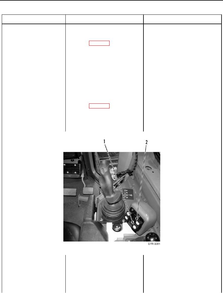
11. Ensure hydraulic lockout switch is
in UNLOCKED (Figure 2, Item 1)
position.
12. Using digital multimeter (WP
1. If continuity is NOT found, replace
0296), test for continuity between
hydraulic lockout switch (WP
pin 4 and 5 on hydraulic lockout
0208). Ensure all harness con-
switch (WP 0018, Figure 91).
nectors are reconnected. Verify
correct operation of machine (TM
5-2410-241-10).
2. If continuity is found, proceed to
step 13.
Figure 2. Hydraulic Lockout Switch.
0021