TM 5-2410-241-23-1
0021
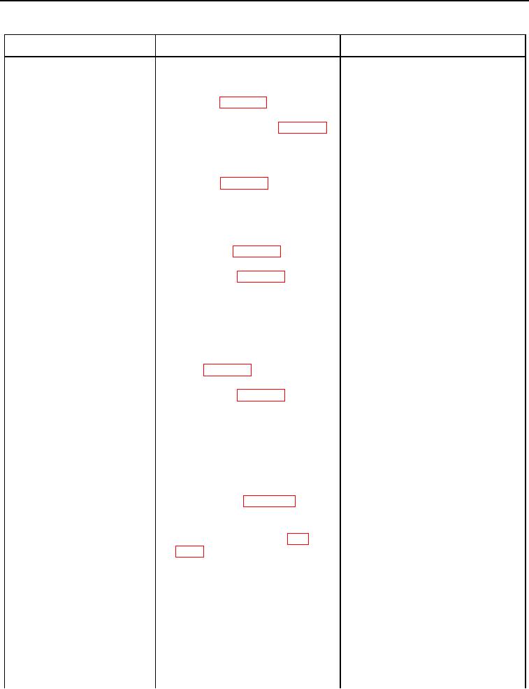
Table 2. Chassis Troubleshooting Procedures - Continued.
0021
MALFUNCTION
TEST OR INSPECTION
CORRECTIVE ACTION
600-4 Hydraulic Oil Temper-
10. Using digital multimeter (WP
1. If continuity is found, replace
ature Sensor Voltage
0296), test for continuity between
chassis harness (WP 0172).
Below Normal - Contin-
pin 6 on chassis harness connec-
Ensure all harness connectors
ued
tor L-C1 (WP 0018, Figure 84)
are reconnected. Verify correct
and all other pins in chassis har-
operation of machine (TM 5-2410-
ness connector L-C1 (WP 0018,
241-10).
Figure 84).
2. If continuity is NOT found, pro-
ceed to step 11.
11. Disconnect dash monitor connec-
tor E-C7 (WP 0018, Figure 5)
from instrument panel (WP 0262).
12. Using digital multimeter (WP
1.
If continuity is NOT found, replace
0296), test for continuity between
platform harness (WP 0209) and
pin 6 on platform harness connec-
instrument panel harness (WP
tor MA-C17 (WP 0018, Figure 85)
0260). Ensure all harness con-
and pin 10 on dash monitor con-
nectors are reconnected. Verify
nector E-C7 (WP 0018, Figure 5).
correct operation of machine (TM
5-2410-241-10).
2. If continuity is found, proceed to
step 13.
13. Using digital multimeter (WP
1.
If continuity is found, replace plat-
0296), test for continuity between
form harness (WP 0209) and
pin 10 on dash monitor connector
instrument panel harness (WP
E-C7 (WP 0018, Figure 5) and all
0260). Ensure all harness con-
other pins in dash monitor con-
nectors are reconnected. Verify
nector E-C7 (WP 0018, Figure 5).
correct operation of machine (TM
5-2410-241-10).
2. If continuity is NOT found, replace
dash monitor ECM (WP 0262).
Ensure all harness connectors
are reconnected. Verify correct
operation of machine (TM 5-2410-
241-10).
600-8 Hydraulic Oil Temper-
1. Connect MSD (WP 0016). Select
1. If active 600-8 code is present,
ature Sensor Voltage
CAT Monitoring System D7R
proceed to step 2.
Abnormal Signal
ECM and check for Diagnostic
2. If no active codes are present, the
Codes or Event Codes (WP
problem does NOT exist at this
time. Resume normal operation.
2. Turn ignition switch and battery
disconnect switch to OFF position
(TM 5-2410-241-10).
3. Remove right side hydraulic tank
access plate (WP 0186).

