
TM 5-2410-241-23-1
0023
FINDING TOP CENTER POSITION FOR NO. 1 AND NO. 6 PISTON
00023
1. Remove engine enclosure left door guard (WP 0202).
2. Remove lower right bolt and rubber bushing from ECM (WP 0101).
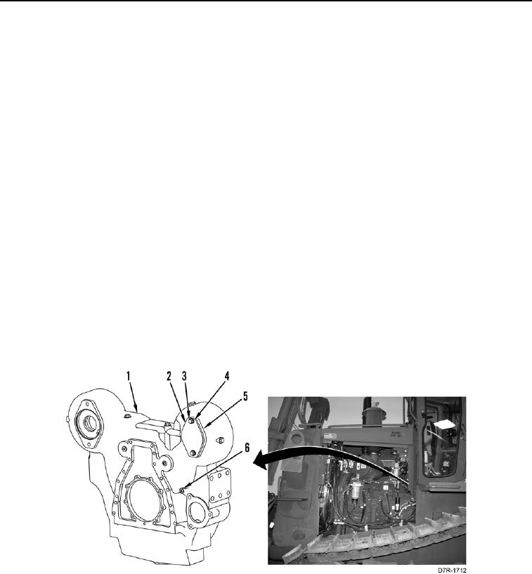
3. Remove plug (Figure 2, Item 6) from flywheel housing (Figure 2, Item 1).
4. Install timing pin adapter and timing pin on flywheel housing (Figure 2, Item 1) in location where plug (Figure 2,
Item 6) was removed.
5. Remove two bolts (Figure 2, Item 3), washers (Figure 2, Item 4), cover (Figure 2, Item 2) and O-ring (Figure 2,
Item 5) from flywheel housing (Figure 2, Item 1). Discard O-ring.
C AU T I O N
Never turn the engine by the crankshaft vibration damper. The crankshaft vibration
damper is a precision part. Major engine failure may be caused by damage to the
crankshaft vibration damper.
6. Install engine turning tool in flywheel housing (Figure 2, Item 1) in location where cover (Figure 2, Item 2) was
removed.
N OT E
Engine must be turned in direction of normal rotation. Normal rotation of the engine is
clockwise viewed from front crankshaft.
7. Using engine turning tool, turn the engine clockwise. Continue rotation clockwise until hole in flywheel aligns
with timing pin. Timing pin will engage automatically.
Figure 2. Timing Pin Plug.
0023