
TM 5-2410-241-23-1
0052
REMOVAL CONTINUED
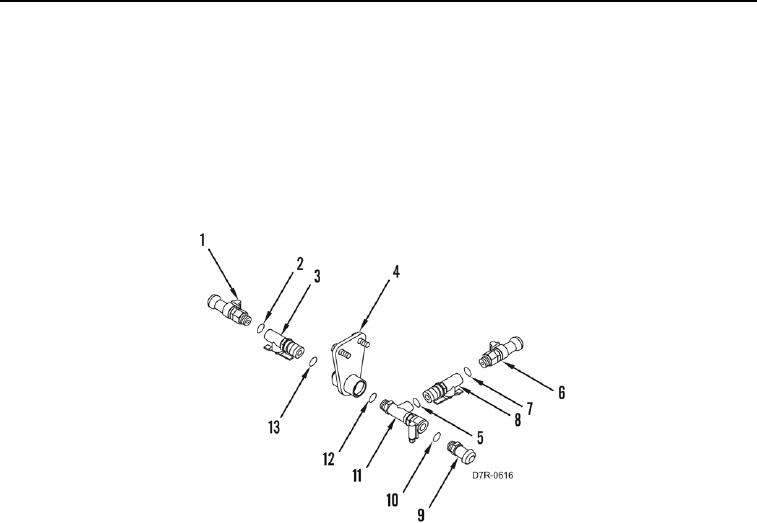
23. Remove fitting (Figure 4, Item 1) and O-ring (Figure 4, Item 2) from valve (Figure 4, Item 3). Discard O-ring.
24. Remove valve (Figure 4, Item 3) and O-ring (Figure 4, Item 13) from coupling (Figure 4, Item 4). Discard O-
ring.
25. Remove fitting (Figure 4, Item 6) and O-ring (Figure 4, Item 7) from valve (Figure 4, Item 8). Discard O-ring.
26. Remove valve (Figure 4, Item 8) and O-ring (Figure 4, Item 5) from tee (Figure 4, Item 11). Discard O-ring.
27. Remove fitting (Figure 4, Item 9) and O-ring (Figure 4, Item 10) from tee (Figure 4, Item 11). Discard O-ring.
28. Remove tee (Figure 4, Item 11) and O-ring (Figure 4, Item 12) from coupling (Figure 4, Item 4). Discard O-ring.
Figure 4. Drain Line Valves.
0052
END OF TASK
CLEANING AND INSPECTION
00052
Clean and inspect all parts IAW Mechanical General Maintenance Instructions (WP 0295).
END OF TASK
INSTALLATION
00052
1. Install new O-ring (Figure 4, Item 12) and tee (Figure 4, Item 11) on coupling (Figure 4, Item 4).
2. Install new O-ring (Figure 4, Item 10) and fitting (Figure 4, Item 9) on tee (Figure 4, Item 11).
3. Install new O-ring (Figure 4, Item 5) and valve (Figure 4, Item 8) on tee (Figure 4, Item 11).
4. Install new O-ring (Figure 4, Item 7) and fitting (Figure 4, Item 6) on valve (Figure 4, Item 8).
5. Install new O-ring (Figure 4, Item 13) and valve (Figure 4, Item 3) and from coupling (Figure 4, Item 4).
6. Install new O-ring (Figure 4, Item 2) and fitting (Figure 4, Item 1) on valve (Figure 4, Item 3).