
TM 5-2410-241-23-1
0052
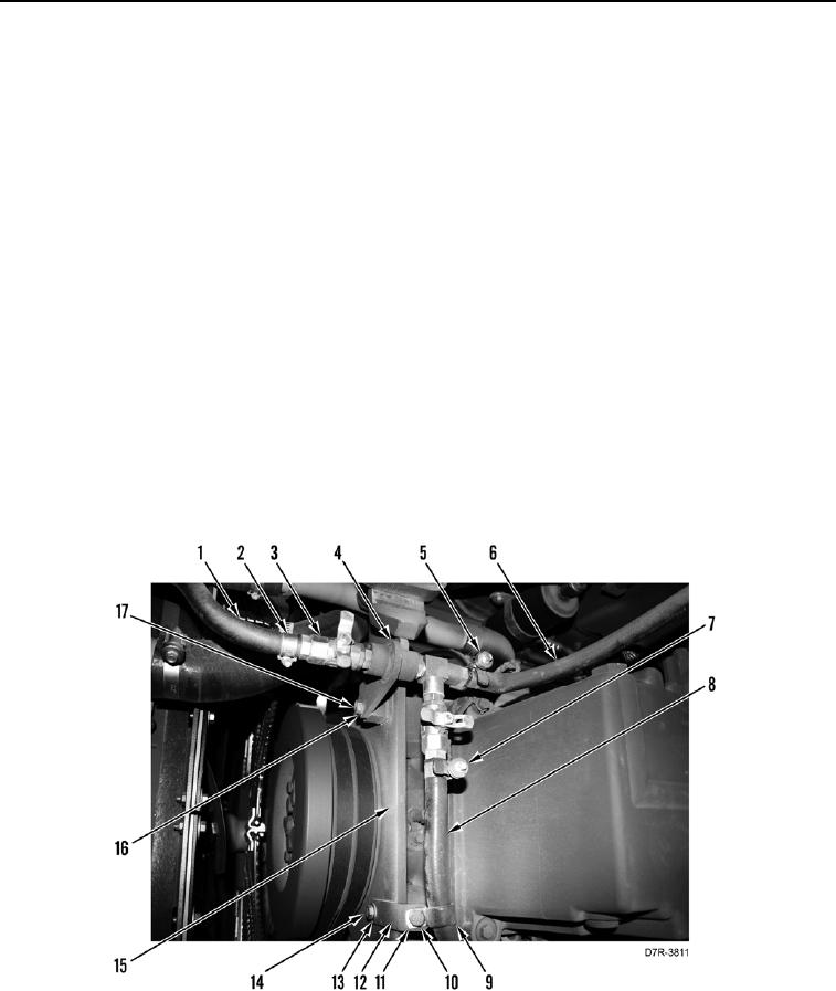
INSTALLATION CONTINUED
N OT E
Install hoses as tagged during removal.
7. Install coupling assembly (Figure 5, Item 4), two washers (Figure 5, Item 16), and bolts (Figure 5, Item 17) on
engine (Figure 5, Item 15).
8. Install clamp (Figure 5, Item 5) on hose (Figure 5, Item 6).
9. Install hose (Figure 5, Item 6) on coupling assembly (Figure 5, Item 4).
10. Tighten clamp (Figure 5, Item 5) on hose (Figure 5, Item 6).
11. Install clamp (Figure 5, Item 2) on hose (Figure 5, Item 1).
12. Install hose (Figure 5, Item 1) on fitting (Figure 5, Item 3).
13. Tighten clamp (Figure 5, Item 2) on hose (Figure 5, Item 1).
14. Install clamp (Figure 5, Item 7) on hose (Figure 5, Item 8).
15. Install hose (Figure 5, Item 8) on coupling assembly (Figure 5, Item 4).
16. Tighten clamp (Figure 5, Item 7) on hose (Figure 5, Item 8).
17. Install three brackets (Figure 5, Item 12), washers (Figure 5, Item 13) and bolts (Figure 5, Item 14) on engine
(Figure 5, Item 15).
18. Install three clamps (Figure 5, Item 9), washers (Figure 5, Item 11) and bolts (Figure 5, Item 10) on hose
(Figure 5, Item 8).
Figure 5. Drain Hoses.
0052