
TM 5-2410-241-23-2
0057
ENGINE REMOVAL CONTINUED
N OT E
Cap and plug all hoses, lines and tubesto prevent contamination and leaks.
Tag and mark all hoses to aid installation.
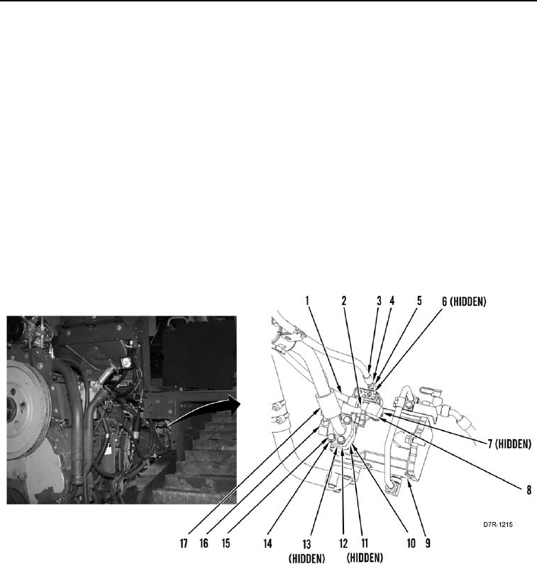
9. Remove four bolts (Figure 5, Item 15), washers (Figure 5, Item 14), split flange clamp (Figure 5, Item 12), hose
(Figure 5, Item 17), O-ring (Figure 5, Item 13), spacer (Figure 5, Item 10), and O-ring (Figure 5, Item 11) from
pump (Figure 5, Item 9). Discard O-rings.
10. Position spacer (Figure 5, Item 10) and hose (Figure 5, Item 16) aside.
11. Loosen tube nut (Figure 5, Item 4) and remove hose (Figure 5, Item 3) from fitting (Figure 5, Item 5). Set hose
aside.
12. Remove fitting (Figure 5, Item 5) and two O-rings (Figure 5, Item 6) from pump (Figure 5, Item 9). Discard O-
rings.
13. Loosen tube nut (Figure 5, Item 2) and remove hose (Figure 5, Item 1) from fitting (Figure 5, Item 8). Set hose
aside.
14. Remove fitting (Figure 5, Item 8) and two O-rings (Figure 5, Item 7) from pump (Figure 5, Item 9). Discard O-
rings.
Figure 5. Pump Hoses.
0057