
TM 5-2410-241-23-2
0057
ENGINE INSTALLATION CONTINUED
N OT E
Remove caps and plugs from all hoses, lines and tubes.
Install all hoses as noted during removal.
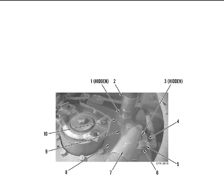
54. Install new O-ring (Figure 64, Item 1), hose (Figure 64, Item 2) and tube nut (Figure 64, Item 10) on torque
converter (Figure 64, Item 8).
55. Position spacer (Figure 64, Item 9) on torque converter (Figure 64, Item 8).
56. Install new O-ring (Figure 64, Item 3), hose (Figure 64, Item 7), split flange clamp (Figure 64, Item 4), four
washers (Figure 64, Item 6), and bolts (Figure 64, Item 5) on torque converter (Figure 64, Item 8).
Figure 64. Torque Converter Hoses.
0057