
TM 5-2410-241-23-2
0057
ENGINE INSTALLATION CONTINUED
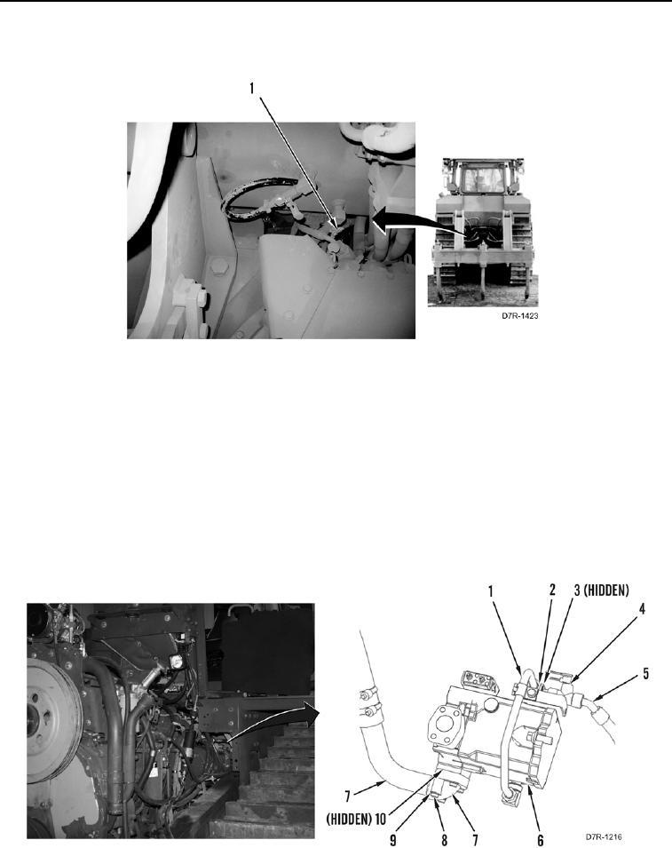
41. Open fuel shutoff valve (Figure 59, Item 1).
Figure 59. Fuel Shutoff Valve.
0057
N OT E
Remove caps and plugs from all hoses, lines and tubes.
Install all hoses as noted during removal.
42. Install new O-ring (Figure 60, Item 3) on tee fitting (Figure 60, Item 4).
43. Install hose (Figure 60, Item 5), two tee fittings (Figure 60, Item 4) and tube nut (Figure 60, Item 2) on line
(Figure 60, Item 1).
44. Install new O-ring (Figure 60, Item 10), line (Figure 60, Item 7), four washers (Figure 60, Item 9), and bolts
(Figure 60, Item 8) on pump (Figure 60, Item 6).
Figure 60. Pump Lines.
0057