
TM 5-2410-241-23-2
0057
ENGINE INSTALLATION CONTINUED
N OT E
Remove caps and plugs from all hoses, lines and tubes.
Install all hoses as noted during removal.
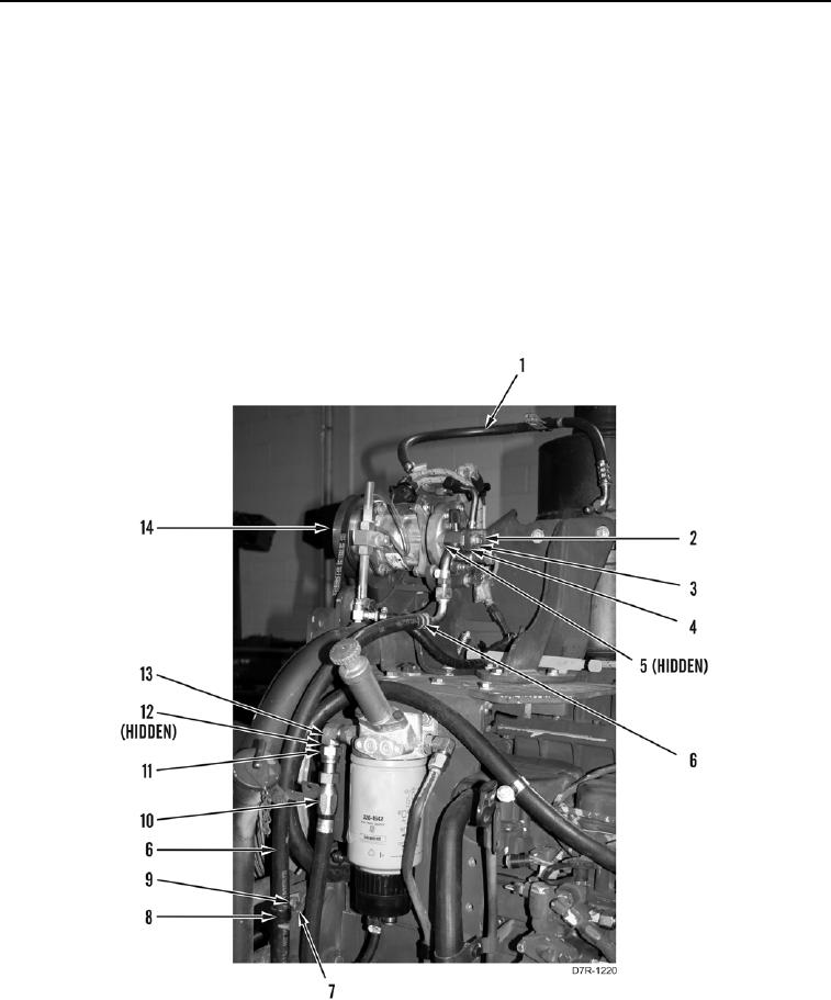
20. Install new O-ring (Figure 55, Item 12), hose (Figure 55, Item 10), and tube nut (Figure 55, Item 11) on fitting
(Figure 55, Item 13).
21. Install two new O-rings (Figure 55, Item 5) and hoses (Figure 55, Items 1 and 6) on A/C compressor (Figure
55, Item 14).
22. Install plate (Figure 55, Item 4), washer (Figure 55, Item 3), and bolt (Figure 55, Item 2) on A/C compressor
(Figure 55, Item 14).
23. Install P-clip (Figure 55, Item 8), washer (Figure 55, Item 9), and bolt (Figure 55, Item 7) on hose (Figure 55,
Item 6).
Figure 55. A/C Hose.
0057