
TM 5-2410-241-23-2
0057
ENGINE INSTALLATION CONTINUED
N OT E
Caps and plugs removed from hoses, lines and tubes.
Install hoses as tagged and marked during removal.
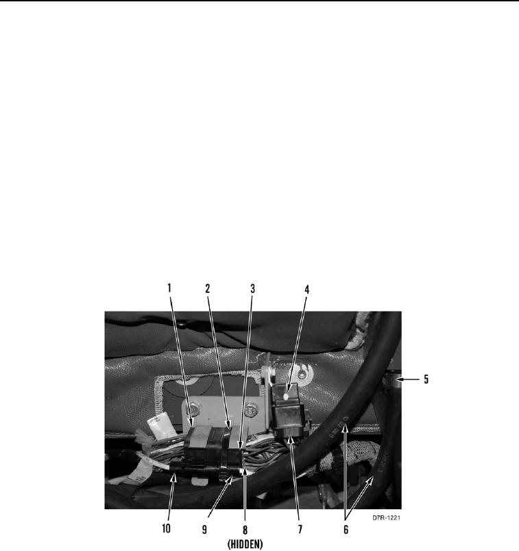
14. Install two heater hoses (Figure 54, Item 6) on cab.
15. install two clamps (Figure 54, Item 5) on heater hoses (Figure 54, Item 6).
N OT E
Install electrical connections and harn ss routing as noted during removal.
e
Install tiedown straps as noted during removal.
16. Connect engine main harness connector (Figure 54, Item 3) and install bolt (Figure 54, Item 8) on platform
connector (Figure 54, Item 1).
17. Connect engine main harness connector (Figure 54, Item 9) on platform connector (Figure 54, Item 10).
18. Connect engine main harness connector (Figure 54, Item 7) on ether aid relay (Figure 54, Item 4).
19. Install new tiedown straps (Figure 54, Item 2) on engine main harness connectors (Figure 54, Items 3 and 9).
Figure 54. Platform Harness Connections.
0057