
TM 5-2410-241-23-2
0057
ENGINE INSTALLATION CONTINUED
N OT E
Connect electrical connections as tagged and marked during removal.
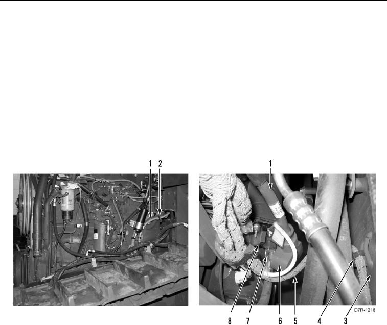
24. Install harness (Figure 56, Item 5) and new tiedown straps (Figure 56, Item 4) on frame (Figure 56, Item 3).
25. Position positive cable (Figure 56, Item 1) on engine.
26. Install new tiedown straps (Figure 56, Item 2) on positive battery cable (Figure 56, Item 1).
27. Remove nut (Figure 56, Item 7) from starter motor solenoid (Figure 56, Item 8).
28. Install positive battery cable (Figure 56, Item 1) and nut (Figure 56, Item 7) on starter motor solenoid
(Figure 56, Item 8).
29. Position boot (Figure 56, Item 6) over nut (Figure 56, Item 7).
Figure 56. Starter Motor.
0057