
TM 5-2410-241-23-2
0059
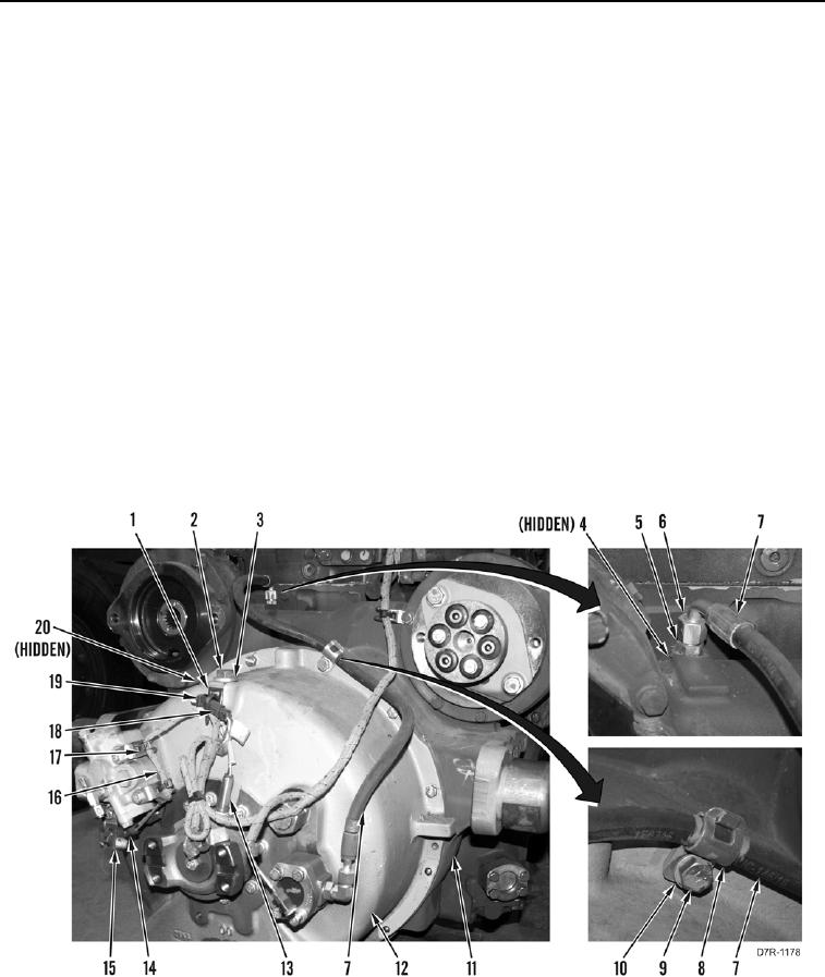
INSTALLATION CONTINUED
N OT E
Torque converter weighs approximately 320 lb (145 kg).
Install bolts as noted during removal.
90. Attach bracket link and lifting device on torque converter (Figure 61, Item 12).
91. Using lifting device, position torque converter (Figure 61, Item 12), hose (Figure 61, Item 7), and clamp
(Figure 61, Item 8), and install ten washers (Figure 61, Item 10) and bolts (Figure 61, Item 9) on engine (Figure
61, Item 11).
92. Remove lifting device and bracket link from torque converter (Figure 61, Item 12).
93. Install clip (Figure 61, Item 1), washer (Figure 61, Item 3), and bolt (Figure 61, Item 2) on torque converter
(Figure 61, Item 12).
94. Install harness (Figure 61, Item 16) and new tiedown straps (Figure 61, Item 17) on torque converter
(Figure 61, Item 12).
95. Connect connector (Figure 61, Item 14) on temperature sensor (Figure 61, Item 15).
96. Connect connector (Figure 61, Item 18) on speed sensor (Figure 61, Item 13).
97. Install new tiedown strap (Figure 61, Item 19) on connector (Figure 61, Item 18).
98. Install two new O-rings (Figure 61, Item 4) and fitting (Figure 61, Item 5) on engine (Figure 61, Item 11).
99. Install hose (Figure 61, Item 7) and tube nut (Figure 61, Item 6) on fitting (Figure 61, Item 5).
Figure 61. Torque Converter.
0059