
TM 5-2410-241-23-2
0074
INSTALLATION
00074
1. Install new O-ring (Figure 2, Item 6) and plug (Figure 2, Item 7) on housing (Figure 2, Item 1).
2. Install new O-ring (Figure 2, Item 8) and plug (Figure 2, Item 9) on housing (Figure 2, Item 1).
3. Install new O-ring (Figure 2, Item 10), fitting (Figure 2, Item 11), new O-ring (Figure 2, Item 12) and fitting
(Figure 2, Item 13) on housing (Figure 2, Item 1).
4. Install cap (Figure 2, Item 14) on fitting (Figure 2, Item 13).
N OT E
Install lip seals and temperature regulators as noted during removal.
If equipped with arctic heater, install arctic temperature regulators.
5. Install two new lip seals (Figure 2, Item 3) and temperature regulators (Figure 2, Item 2) on housing (Figure 2,
Item 1).
6. Install new gasket (Figure 2, Item 4) on coolant manifold (Figure 2, Item 5).
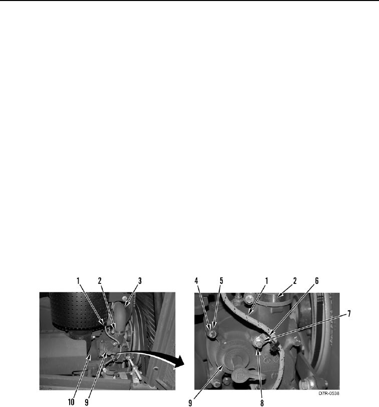
7. Install housing (Figure 3, Item 9), six washers (Figure 3, Item 5), and bolts (Figure 3, Item 4) on engine (Figure
3, Item 10).
N OT E
Install hoses as tagged during removal.
8. Install hose (Figure 3, Item 3) and clamp (Figure 3, Item 2) on housing (Figure 3, Item 9).
9. Position harness (Figure 3, Item 1) on housing (Figure 3, Item 9).
10. Install two clips (Figure 3, Item 6), washers (Figure 3, Item 7), and nuts (Figure 3, Item 8) on housing (Figure 3,
Item 9).
Figure 3. Housing.
0074
END OF TASK