
TM 5-2410-241-23-2
0075
REMOVAL
00075
N OT E
Tag electrical connectors to aid installation.
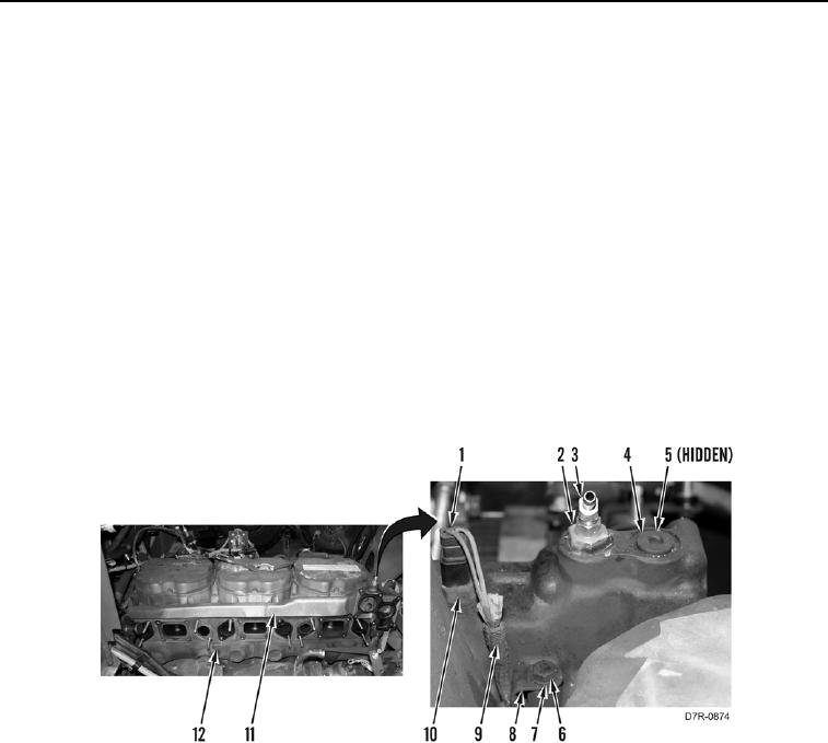
1. Disconnect connector (Figure 1, Item 1) from coolant temperature sensor (Figure 1, Item 10).
2. Remove coolant temperature sensor (Figure 1, Item 10) from cooling manifold (Figure 1, Item 11).
3. Remove plug (Figure 1, Item 4) and O-ring (Figure 1, Item 5) from cooling manifold (Figure 1, Item 11). Discard
O-ring.
4. Remove fitting (Figure 1, Item 3) from fitting (Figure 1, Item 2).
5. Remove fitting (Figure 1, Item 2) from cooling manifold (Figure 1, Item 11).
N OT E
Note location and size of bolts to aid in installation.
6. Remove eight bolts (Figure 1, Item 6), washers (Figure 1, Item 7), clip (Figure 1, Item 8), and cooling manifold
(Figure 1, Item 11) from engine (Figure 1, Item 12). Position harness (Figure 1, Item 9) aside.
Figure 1. Coolant Temperature Sensor.
0075