
TM 5-2410-241-23-2
0075
REMOVAL CONTINUED
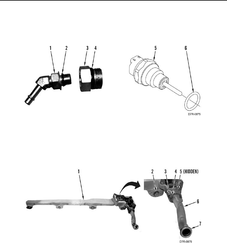
7. Remove O-ring (Figure 2, Item 6) from coolant temperature sensor (Figure 2, Item 5). Discard O-ring.
8. Remove O-ring (Figure 2, Item 2) from fitting (Figure 2, Item 1). Discard O-ring.
9. Remove O-ring (Figure 2, Item 4) from fitting (Figure 2, Item 3). Discard O-ring.
Figure 2. Coolant Temperature Sensor O-ring.
0075
10. Remove four gaskets (Figure 3, Item 2) from cooling manifold (Figure 3, Item 1). Discard gaskets.
11. Remove two bolts (Figure 3, Item 3), washers (Figure 3, Item 4), pipe (Figure 3, Item 6), and gasket (Figure 3,
Item 5) from cooling manifold (Figure 3, Item 1). Discard gasket.
12. Remove two O-rings (Figure 3, Item 7) from pipe (Figure 3, Item 6). Discard O-rings.
Figure 3. Cooling Manifold Gaskets.
0075
END OF TASK
CLEANING AND INSPECTION
00075
Clean and inspect all parts IAW Mechanical General Maintenance Instructions (WP 0295).
END OF TASK