
6
TM 5-2410-241-23-2
FIELD MAINTENANCE
-
WATER PUMP ELBOW REPLACEMENT
00
76
Removal, Cleaning and Inspection, Installation
INITIAL SETUP
Equipment Condition
Tools and Special Tools
0
0
Tool Kit, General Mechanic's
Machine parked (TM 5-2410-241-10)
0
(WP 0302, Item 65)
Engine enclosure right door guard removed
0
(WP 0204)
0
Materials/Parts
0
Cooling system drained (WP 0113)
0
Rag, Wiping (WP 0303, Item 24)
0
Drawing Required
Tag, Marker (WP 0303, Item 34)
0
0
Gasket
TM 5-2410-241-24P, Figure 5, 29, 101
0
0
O-ring (4)
0
Estimated Time to Complete
0
4.0 Hr
References
0
0
WP 0295
0
REMOVAL
00076
N OT E
Tag and note routing and position of hoses to aid installation.
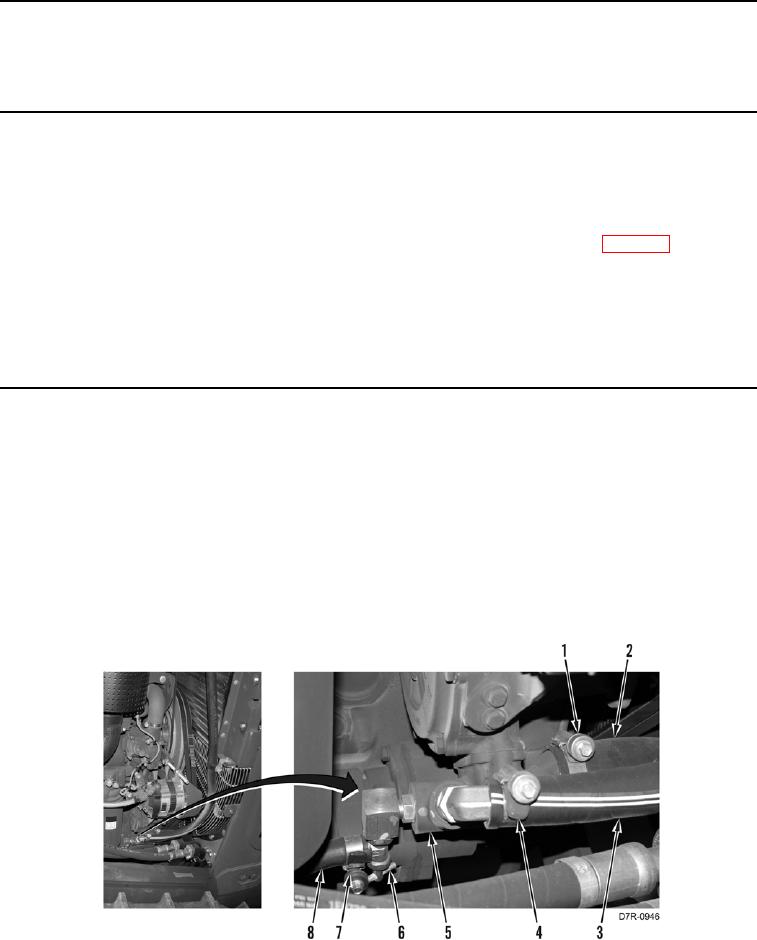
1. Loosen clamp (Figure 1, Item 1) and remove hose (Figure 1, Item 2) from elbow (Figure 1, Item 5).
2. Remove clamp (Figure 1, Item 1) from hose (Figure 1, Item 2). Position hose aside.
3. Loosen clamp (Figure 1, Item 4) and remove hose (Figure 1, Item 3) from fitting (Figure 1, Item 5).
4. Remove clamp (Figure 1, Item 4) from hose (Figure 1, Item 3). Position hose aside.
5. Loosen clamp (Figure 1, Item 7) and remove hose (Figure 1, Item 8) from valve (Figure 1, Item 6).
6. Remove clamp (Figure 1, Item 7) from hose (Figure 1, Item 8). Position hose aside.
Figure 1. Hoses to Elbow.
0076