
TM 5-2410-241-23-2
0093
REMOVAL CONTINUED
N OT E
Tag electrical connectors to aid installation.
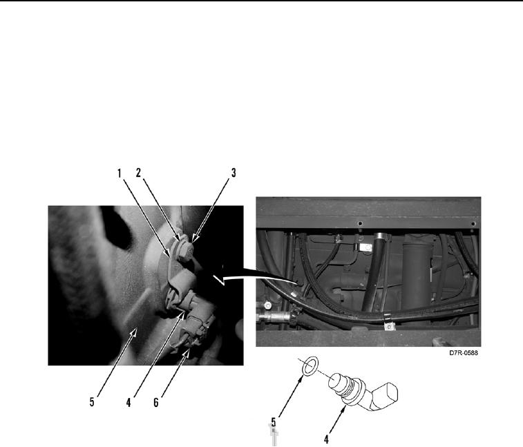
2. Disconnect connector (Figure 2, Item 6) from camshaft timing sensor (Figure 2, Item 4).
3. Remove bolt (Figure 2, Item 3), washer (Figure 2, Item 2), clamp (Figure 2, Item 1) and camshaft timing sensor
(Figure 2, Item 4) from engine (Figure 2, Item 5).
4. Remove O-ring (Figure 2, Item 5) from camshaft timing sensor (Figure 2, Item 4). Discard O-ring.
Figure 2. Camshaft Timing Sensor.
0093
END OF TASK
CLEANING AND INSPECTION
00093
Clean and inspect all parts IAW Mechanical General Maintenance Instructions (WP 0295).
END OF TASK