
TM 5-2410-241-23-2
0094
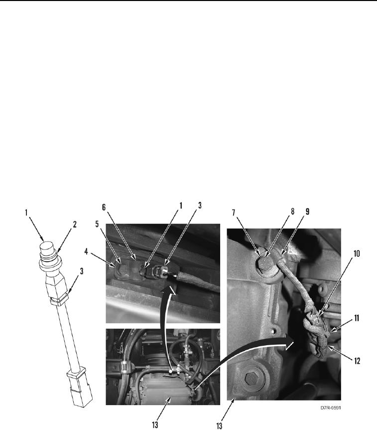
REMOVAL
00094
C AU T I O N
Do not disconnect jumper harness from sensor. Sensor damage will occur.
1. Do not disconnect connector (Figure 1, Item 3) from engine crankshaft position sensor (Figure 1, Item 1).
N OT E
Tag electrical connectors to aid installation.
2. Remove tiedown strap (Figure 1, Item 11) and disconnect connector (Figure 1, Item 10) from harness
(Figure 1, Item 12). Discard tiedown strap.
3. Remove bolt (Figure 1, Item 8), washer (Figure 1, Item 7) and clamp (Figure 1, Item 9) from engine (Figure 1,
Item 13).
4. Remove bolt (Figure 1, Item 5), washer (Figure 1, Item 4), clamp (Figure 1, Item 6) and engine crankshaft
position sensor (Figure 1, Item 1) from engine (Figure 1, Item 13).
5. Remove O-ring (Figure 1, Item 2) from engine crankshaft position sensor (Figure 1, Item 1). Discard O-ring.
Figure 1. Engine Crankshaft Position Sensor.
0094
END OF TASK