
TM 5-2410-241-23-2
0097
INSTALLATION CONTINUED
N OT E
Install bolts, nuts and brackets as noted during removal.
Install pulley with same clearance as noted during removal.
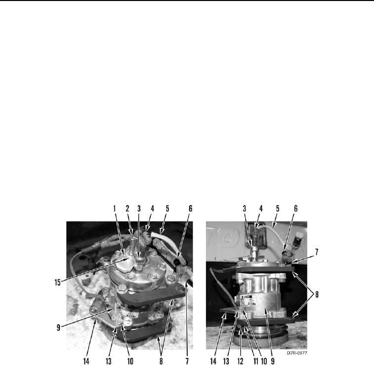
10. Install adjustment bracket (Figure 8, Item 14), two mounting brackets (Figure 8, Item 8), one harness clip
(Figure 8, Item 7), five washer (Figure 8, Item 13), bolts (Figure 8, Item 10), washers (Figure 8, Item 11), and
nuts (Figure 8, Item 12) on compressor (Figure 8, Item 9).
11. Install switch (Figure 8, Item 3) on compressor (Figure 8, Item 9).
12. Install new tiedown strap (Figure 8, Item 6) on harness (Figure 8, Item 5).
N OT E
Tag and mark electrical connectors to aid installation.
13. Connect connector (Figure 8, Item 4) on switch (Figure 8, Item 3).
14. Install plate (Figure 8, Item 1), washer (Figure 8, Item 15), and bolt (Figure 8, Item 2) on compressor (Figure 8,
Item 9).
Figure 8. A/C Compressor Mounts.
0097