
TM 5-2410-241-23-2
0097
INSTALLATION CONTINUED
N OT E
Install electrical connectors as noted during removal.
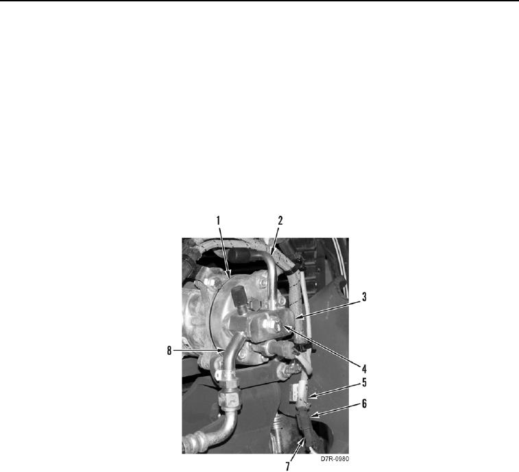
18. Position harness (Figure 10, Item 5) on machine.
19. Connect connector (Figure 10, Item 6) on connector (Figure 10, Item 7).
N OT E
Install lines as tagged during removal.
20. Install line (Figure 10, Item 8), line (Figure 10, Item 2), position plate (Figure 10, Item 3) as shown and tighten
bolt (Figure 10, Item 4) on A/C compressor (Figure 10, Item 1).
Figure 10. Compressor Lines.
0097