
TM 5-2410-241-23-2
0097
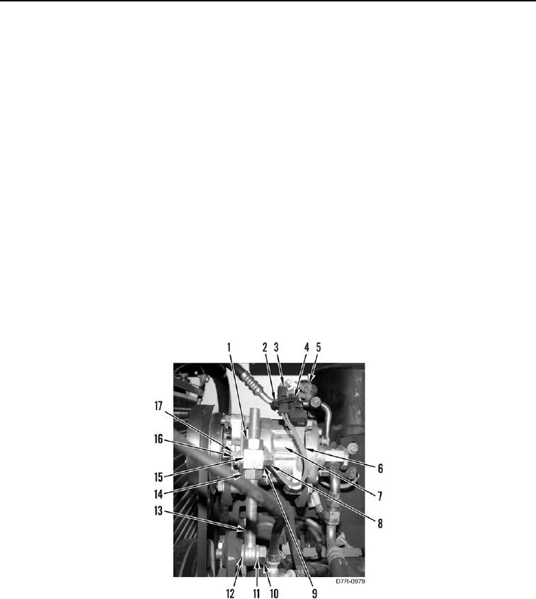
INSTALLATION CONTINUED
21. Install nut (Figure 11, Item 14), block (Figure 11, Item 15), and nut (Figure 11, Item 1) on shaft (Figure 11,
Item 13).
22. Install washer (Figure 11, Item 12), shaft (Figure 11, Item 13), washer (Figure 11, Item 11), and bolt (Figure 11,
Item 10) on A/C compressor (Figure 11, Item 7).
23. Install washer (Figure 11, Item 17), bolts (Figure 11, Item 16), washer (Figure 11, Item 9), and nut (Figure 11,
Item 8) on block (Figure 11, Item 15). Do not tighten bolt and nut.
N OT E
Ensure belt is aligned on pulleys.
Adjust belt with nuts as noted during removal.
24. Adjust nut (Figure 11, Item 1), block (Figure 11, Item 15) and nut (Figure 11, Item 14) on shaft (Figure 11,
Item 13).
N OT E
Install electrical connectors as noted during removal.
25. Position harness (Figure 11, Item 5) and harness (Figure 11, Item 6) on A/C compressor (Figure 11, Item 7).
26. Connect connector (Figure 11, Item 3) on connector (Figure 11, Item 2).
27. Install new tiedown strap (Figure 11, Item 4) on connector (Figure 11, Item 2).
Figure 11. Compressor Adjusting Shaft.
0097