
TM 5-2410-241-23-2
0106
VALVE MECHANISM BASE AND INJECTOR HARNESS INSTALLATION
000106
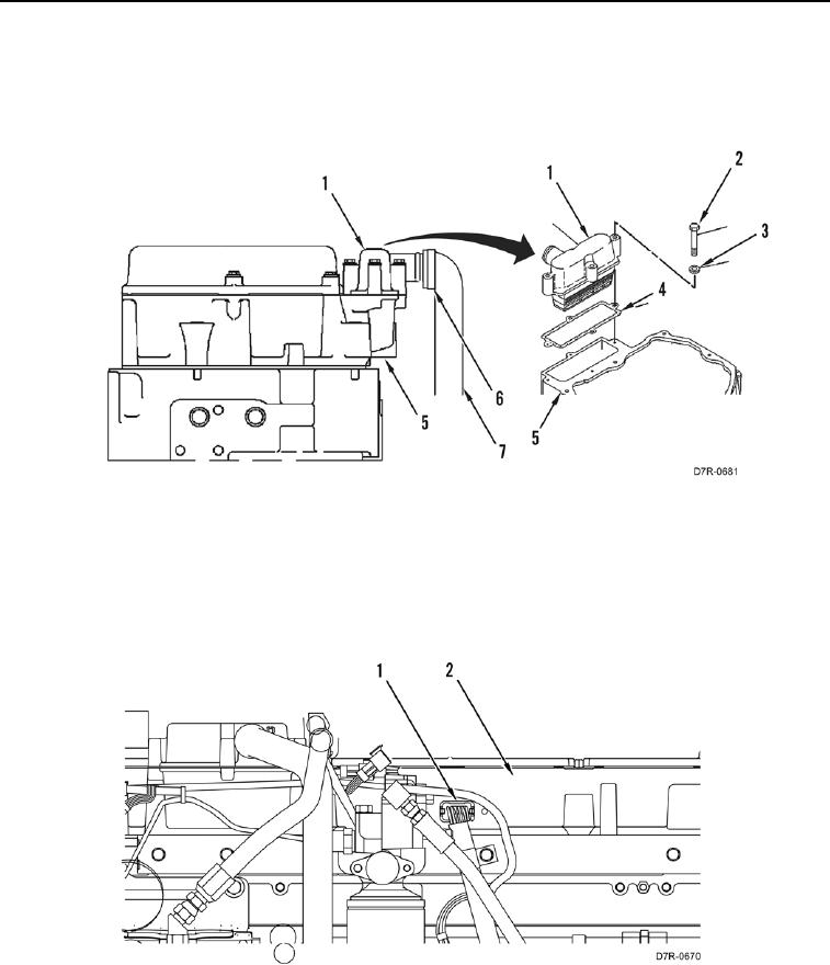
13. Install new gasket (Figure 14, Item 4), crankcase breather (Figure 14, Item 1), four washers (Figure 14,
Item 3), and bolts (Figure 14, Item 2) on valve cover base (Figure 14, Item 5).
14. Install hose (Figure 14, Item 7) and clamp (Figure 14, Item 6) on crankcase breather (Figure 14, Item 1).
Figure 14. Crankcase Breather.
00106
N OT E
Install electrical connector as noted during removal.
15. Connect connector (Figure 15, Item 1) on valve cover base (Figure 15, Item 2).
Figure 15. Harness Connector.
00106