• Home
  • Download PDF
  • Order CD-ROM
  • Order in Print
Figure 11. Valve Cover Base.
Figure 13. Atmospheric Pressure Sensor.

Field Maintenance Manual D7R Dozer Type I With Winch and Type II With Ripper
Page Navigation
  457    458    459    460    461  462  463    464    465    466    467  
img
.
TM 5-2410-241-23-2
0106
VALVE MECHANISM BASE AND INJECTOR HARNESS INSTALLATION
000106
N OT E
Install electrical connectors as noted from removal.
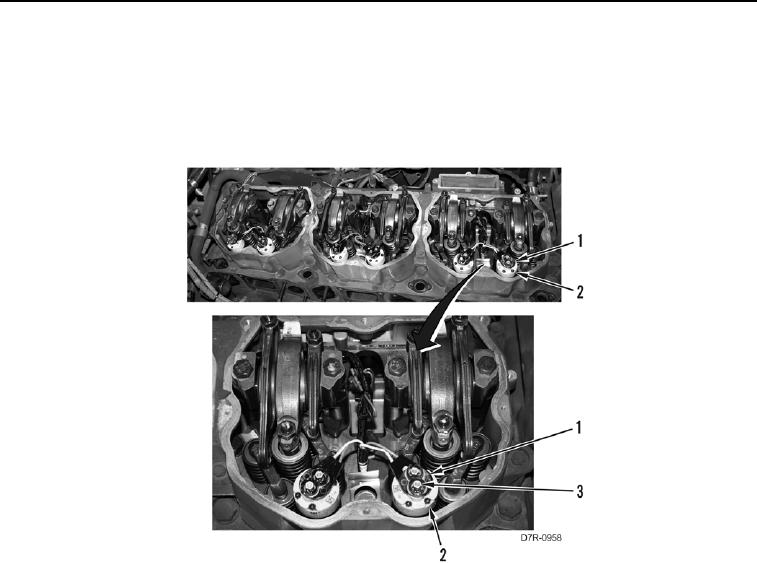
6. Install 6 connectors (Figure 12, Item 1) and 12 nuts (Figure 12, Item 3) on 6 injectors (Figure 12, Item 2).
Figure 12. Injectors.
00106
0106-12


Privacy Statement
Press Release
Contact

© Copyright Integrated Publishing, Inc.. All Rights Reserved.