
TM 5-2410-241-23-2
0106
VALVE MECHANISM BASE AND INJECTOR HARNESS INSTALLATION
000106
N OT E
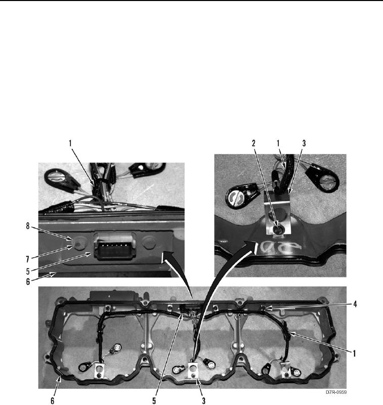
Note position of harness clips and harness routing to aid installation.
1. Install four harness clips (Figure 10, Item 4) and three crimp style clips (Figure 10, Item 3) on harness
(Figure 10, Item 1).
2. Install harness (Figure 10, Item 1), four harness clips (Figure 10, Item 4), three crimp style clips (Figure 10,
Item 3), and seven bolts (Figure 10, Item 2) on valve mechanism cover base (Figure 10, Item 6).
3. Install connector (Figure 10, Item 5) two washers (Figure 10, Item 8), and bolts (Figure 10, Item 7) on valve
mechanism cover base (Figure 10, Item 6).
Figure 10. Injector Harness.
00106