
TM 5-2410-241-23-2
0106
VALVE MECHANISM BASE AND INJECTOR HARNESS REMOVAL CONTINUED
000106
N OT E
Tag and mark all electrical connectors to aid installation.
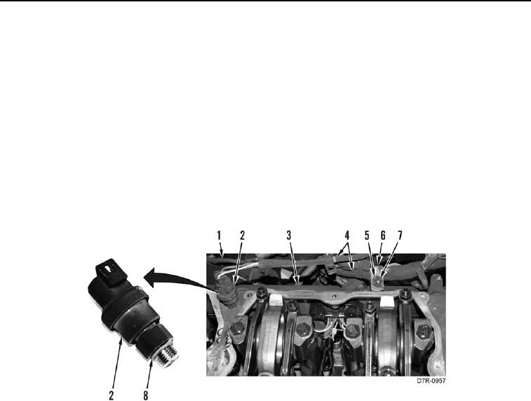
6. Disconnect connector (Figure 6, Item 1) from pressure sensor (Figure 6, Item 2).
7. Remove pressure sensor (Figure 6, Item 2) from valve mechanism cover base (Figure 6, Item 3).
8. Remove O-ring (Figure 6, Item 8) from pressure sensor (Figure 6, Item 2). Discard O-ring.
9. Remove three bolts (Figure 6, Item 7), washers (Figure 6, Item 5), and harness clips (Figure 6, Item 6) from
valve mechanism cover base (Figure 6, Item 3).
10. Remove three harness clips (Figure 6, Item 6) from harness (Figure 6, Item 4).
11. Position harness (Figure 6, Item 4) aside.
Figure 6. Atmospheric Pressure Sensor.
00106