• Home
  • Download PDF
  • Order CD-ROM
  • Order in Print
Figure 6. Atmospheric Pressure Sensor.
Figure 8. Valve Cover Base.

Field Maintenance Manual D7R Dozer Type I With Winch and Type II With Ripper
Page Navigation
  452    453    454    455    456  457  458    459    460    461    462  
img
.
TM 5-2410-241-23-2
0106
VALVE MECHANISM BASE AND INJECTOR HARNESS REMOVAL CONTINUED
000106
N OT E
Tag and mark all electrical connectors to aid installation.
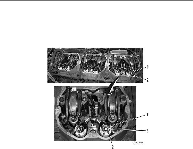
12. Remove 12 nuts (Figure 7, Item 3) and 6 connectors (Figure 7, Item 1) from 6 injectors (Figure 7, Item 2).
Position connectors (Figure 7, Item 1) aside.
Figure 7. Injectors.
00106
0106-7


Privacy Statement
Press Release
Contact

© Copyright Integrated Publishing, Inc.. All Rights Reserved.