
TM 5-2410-241-23-2
0106
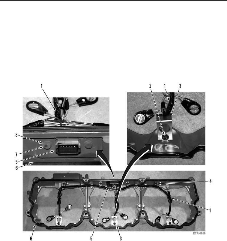
VALVE MECHANISM BASE AND INJECTOR HARNESS REMOVAL CONTINUED
000106
15. Remove two bolts (Figure 9, Item 7), washers (Figure 9, Item 8), and connector (Figure 9, Item 5) from valve
mechanism cover base (Figure 9, Item 6). Position connector (Figure 9, Item 5) aside.
N OT E
Note position of harness clips and harness routing to aid installation.
16. Remove seven bolts (Figure 9, Item 2), three crimp style clips (Figure 9, Item 3), four harness clips (Figure 9,
Item 4), and harness (Figure 9, Item 1) from valve mechanism cover base (Figure 9, Item 6).
17. Remove three crimp style clips (Figure 9, Item 3), and four harness clips (Figure 9, Item 4) from harness
(Figure 9, Item 1).
Figure 9. Injector Harness.
00106
END OF TASK
CLEANING AND INSPECTION
000106
Clean and inspect all parts IAW Mechanical General Maintenance Instructions (WP 0295).
END OF TASK