
TM 5-2410-241-23-2
0141
REMOVAL CONTINUED
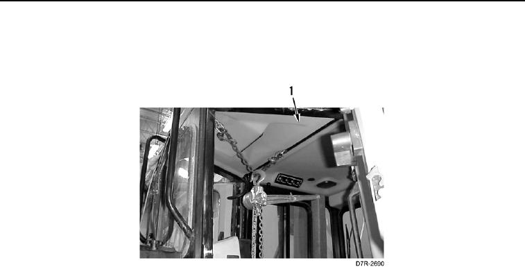
10. Install bracket links on cab (Figure 4, Item 1).
11. Install chain hoist on bracket links.
Figure 4. Cab Lifting Device Setup.
0141
C AU T I O N
Cap all hose and tube ends along with component connections during removal to protect
against contamination. Failure to follow this caution may cause damage to equipment.
N OT E
Tag all hoses, tubes, and fittings to aid installation.
Use a container to catch any fluid that maydrain from hoses or system. Dispose of fluid
IAW local policy and ordinances. Ensure all spills are cleaned up.
Note routing of hoses and lines to aid installation.