• Home
  • Download PDF
  • Order CD-ROM
  • Order in Print
Figure 28. Elbow.
Figure 31. Hose Assemblies.

Field Maintenance Manual D7R Dozer Type I With Winch and Type II With Ripper
Page Navigation
  784    785    786    787    788  789  790    791    792    793    794  
img
.
TM 5-2410-241-23-2
0148
INSTALLATION CONTINUED
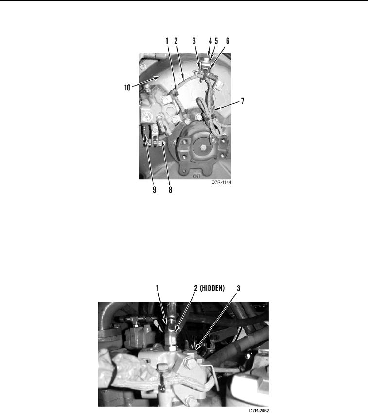
Figure 29. Wiring Harness.
0148
N OT E
Install hoses as tagged during removal.
35. Install new O-ring (Figure 30, Item 2) and hose assembly (Figure 30, Item 1) on torque converter outlet relief
valve (Figure 30, Item 3).
Figure 30. Outlet Relief Valve.
0148
0148-23


Privacy Statement
Press Release
Contact

© Copyright Integrated Publishing, Inc.. All Rights Reserved.