
TM 5-2410-241-23-2
0148
INSTALLATION CONTINUED
WARN I N G
Use extreme caution when handling heavy parts. Provide adequate support and use
assistance during procedure. Ensure lifting device used is in good condition and of
suitable load capacity. Keep clear of heavy parts supported only by lifting device. Failure
to follow this warning may cause injury or death to personnel.
N OT E
Torque converter weighs approximately 320 lb (145 kg).
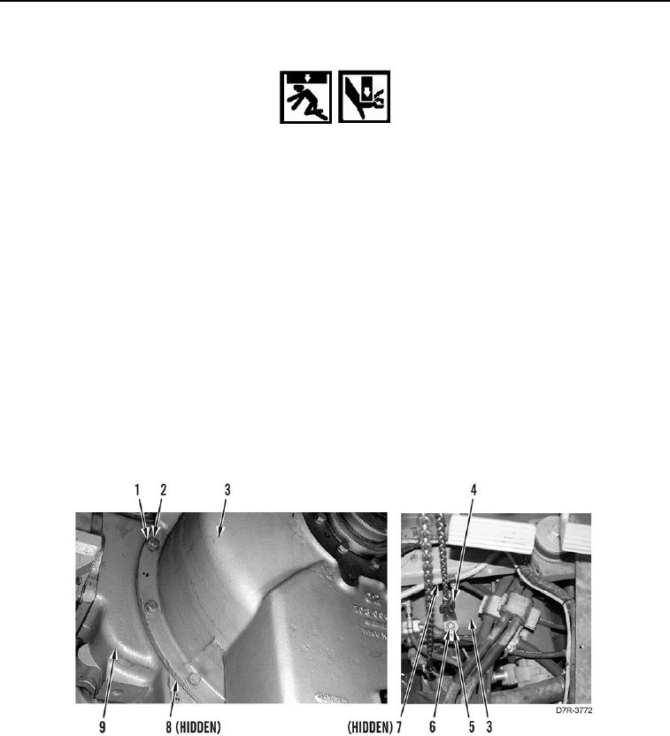
17. Install new O-ring seal (Figure 25, Item 8) on torque converter housing (Figure 25, Item 3).
18. Attach lifting device on bracket link (Figure 25, Item 4) and torque converter housing (Figure 25, Item 3).
19. Using lifting device, position torque converter housing (Figure 25, Item 3) under bottom of machine.
20. With assistance and using lifting device, install torque converter housing (Figure 25, Item 3) on engine
(Figure 25, Item 9).
21. Install clamp (Figure 25, Item 7), 10 washers (Figure 25, Item 2) and bolts (Figure 25, Item 1) on torque
converter housing (Figure 25, Item 3).
22. Remove lifting device from bracket link (Figure 25, Item 4).
23. Remove bolt (Figure 25, Item 6), washer (Figure 25, Item 5), and bracket link (Figure 25, Item 4) from torque
converter housing (Figure 25, Item 3).
Figure 25. Torque Converter Housing.
0148