
TM 5-2410-241-23-2
0153
REMOVAL CONTINUED
N OT E
Tag electrical connectors and lines to aid installation.
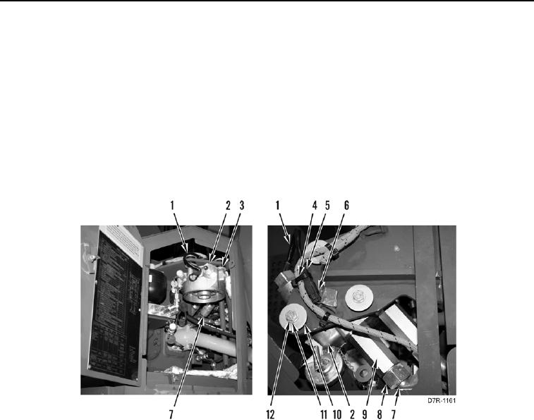
1. Remove tiedown strap (Figure 1, Item 4) from connector (Figure 1, Item 5).
2. Disconnect connector (Figure 1, Item 6) from connector (Figure 1, Item 5) and position harness (Figure 1,
Item 1) aside.
3. Loosen two tube nuts (Figure 1, Item 8) and lines (Figure 1, Item 7) from fittings (Figure 1, Item 9).
4. Remove three bolts (Figure 1, Item 12), washers (Figure 1, Item 11), large washers (Figure 1, Item 10), filter
base (Figure 1, Item 2), and large washers (Figure 1, Item 3) from machine.
Figure 1. Transmission Filter Base.
0153