
TM 5-2410-241-23-2
0153
INSTALLATION CONTINUED
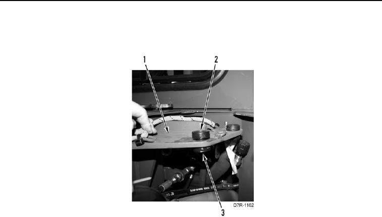
6. Install three lower isolators (Figure 7, Item 3) and upper isolators (Figure 7, Item 2) on bracket (Figure 7,
Item 1).
Figure 7. Transmission Filter Base Isolators.
0153
7. Install three large washers (Figure 8, Item 3), filter base (Figure 8, Item 2), three large washers (Figure 8,
Item 10), washers (Figure 8, Item 11), and bolts (Figure 8, Item 12) on machine.
N OT E
Install electrical connectors and lines as tagged during removal.
8. Install two lines (Figure 8, Item 7) and tube nuts (Figure 8, Item 8) on fittings (Figure 8, Item 9).
9. Position harness (Figure 8, Item 1) on machine.