
TM 5-2410-241-23-2
0153
INSTALLATION
000153
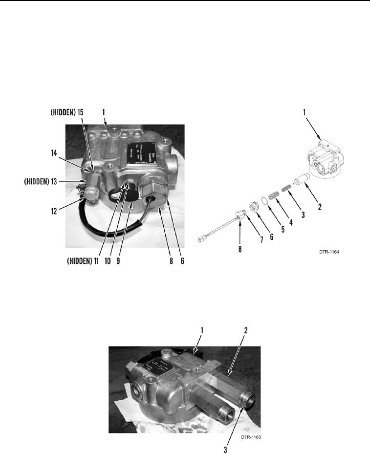
1. Install spool valve (Figure 5, Item 2), springs (Figure 5, Items 3 and 4), new O-ring (Figure 5, Item 5), and fitting
(Figure 5, Item 6) on filter base (Figure 5, Item 1).
2. Install new O-ring (Figure 5, Item 7) and bypass switch (Figure 5, Item 8) on filter base (Figure 5, Item 1).
3. Install new O-ring (Figure 5, Item 15), fitting (Figure 5, Item 14), new O-ring (Figure 5, Item 13), and valve
(Figure 5, Item 12) on filter base (Figure 5, Item 1).
4. Install new O-ring (Figure 5, Item 11), fitting (Figure 5, Item 10), and cap (Figure 5, Item 9) on filter base
(Figure 5, Item 1).
Figure 5. Transmission Filter Base Bypass Switch.
0153
5. Install four new O-rings (Figure 6, Item 3) and two fittings (Figure 6, Item 2) on from filter base (Figure 6,
Item 1).
Figure 6. Transmission Filter Base Fittings.
0153