
TM 5-2410-241-23-3
0205
INSTALLATION CONTINUED
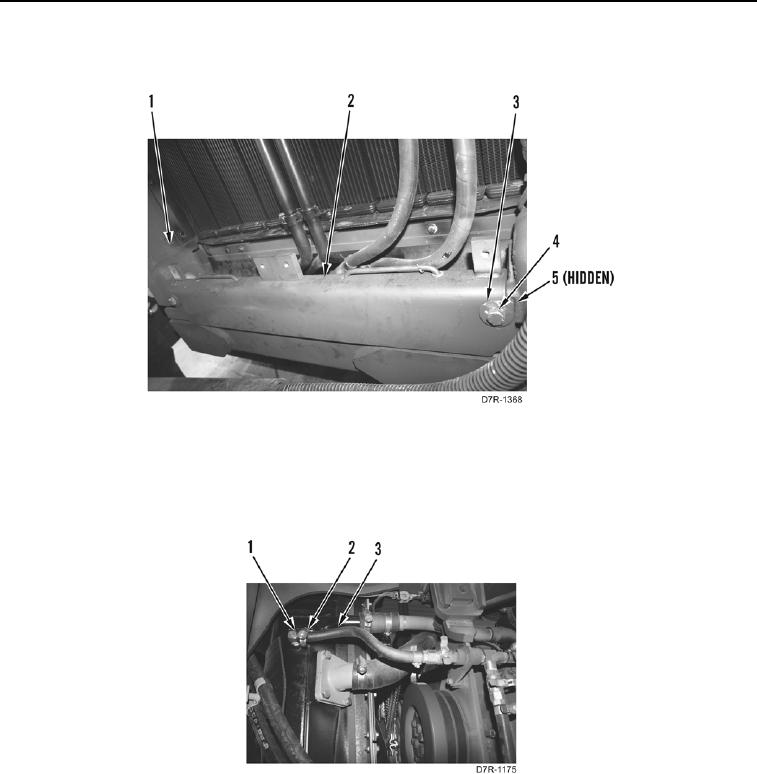
16. Install plate (Figure 18, Item 2), two spacers (Figure 18, Item 5), washers (Figure 18, Item 3), and bolts
(Figure 18, Item 4) on radiator guard (Figure 18, Item 1).
Figure 18. Plate.
0205
17. Install clamp (Figure 19, Item 2) on hose (Figure 19, Item 3).
18. Install hose (Figure 19, Item 3) on fitting (Figure 19, Item 1).
19. Tighten clamp (Figure 19, Item 2) on hose (Figure 19, Item 3).
Figure 19. Radiator Drain Hose and Fitting.
0205
20. Fill hydraulic tank (WP 0184).
21. Install cooling fan (WP 0050).
22. Install vent line (WP 0051).
23. Install water tank outlet hose (WP 0051).
24. Install water pump inlet hose (WP 0051).
25. Install water temperature regulator outlet hose (WP 0051).
26. Install after cooler inlet hoses and pipe (WP 0051).