
TM 5-2410-241-23-3
0206
INSTALLATION CONTINUED
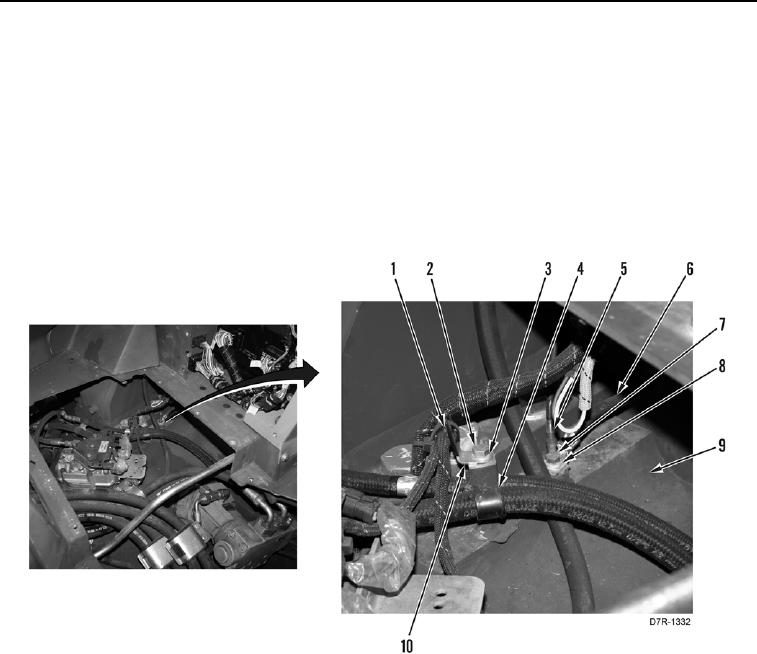
20. Install bracket (Figure 27, Item 10), clamp (Figure 27, Item 4), washer (Figure 27, Item 3), and bolt (Figure 27,
Item 2) on chassis (Figure 27, Item 9).
N OT E
Install wires as tagged during removal.
21. Connect two ground wires (Figure 27, Items 5 and 6) on chassis (Figure 27, Item 9) and install washer
(Figure 27, Item 8) and bolt (Figure 27, Item 7).
22. Install new tiedown strap (Figure 27, Item 1) on bracket (Figure 27, Item 10).
Figure 27. Brake Solenoid Wiring.
0206